Application of DCS in Plant Automation
- The power generation in a power plant consists of several major process units.
- Depending upon individual pieces of plant equipment this process is classified as sub-processes.
- For a power plant, the DCS architecture must match the process structure to provide integrated monitoring and control.
- Automation and functions such as automatic boiler control, burner management system, turbine speed, and load control, sequential control and protection, and interlock logic.
- The application of DCS in power plants should result in higher plant efficiency.
Automation Structure
The below figure shows the automation structure for power plant control
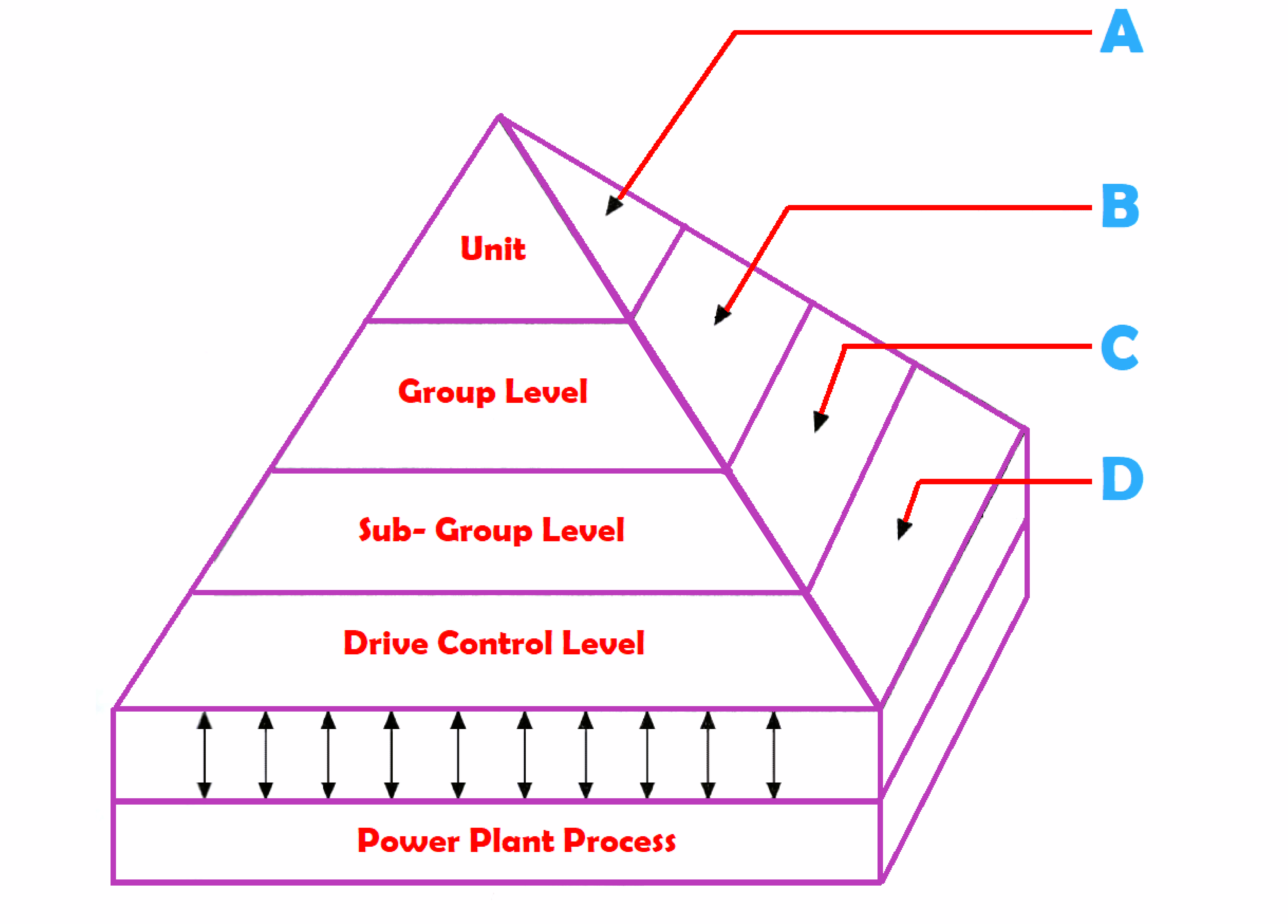
| S.No. | Function | Structure |
| A | Monitoring, Logging, Adv. control man-machine Communication | Distributed over centrally located computers |
| B | Modulating and Binary control | Microcomputers distributed over groups |
| C | Modulating and Binary control | Microcomputers distributed over groups |
| D | Basic logic, protection, and Equipment drive. | Microprocessors’ solid-state distributed overdrives |
Drive Control Level
This level performs the basic logic, driving, and protection for the pump, valve, or damper.
Sub-Group and Group Level
This level performs modulating and binary control functions for a sub-process. For example, A sub-group controller for feed water controls all the feed pumps. The sub-group controller acts on the drive controllers.
A Unit Master Controller (UMC) controls and coordinates the total plant and commands the lower levels.
It essentially controls plant start-up and shutdown and coordinates the plant processes during the load variation.
Unit Level
These computers collect all relevant power plant data, alarm reports, and log data for providing historical storage, and performance calculations.
The entire plant system is interconnected by a hierarchical bus system.
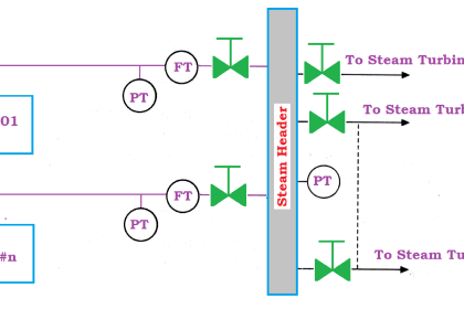
The Hardware Structure of DCS
The below figure represents the typical structure of DCS application in all power plant automation.
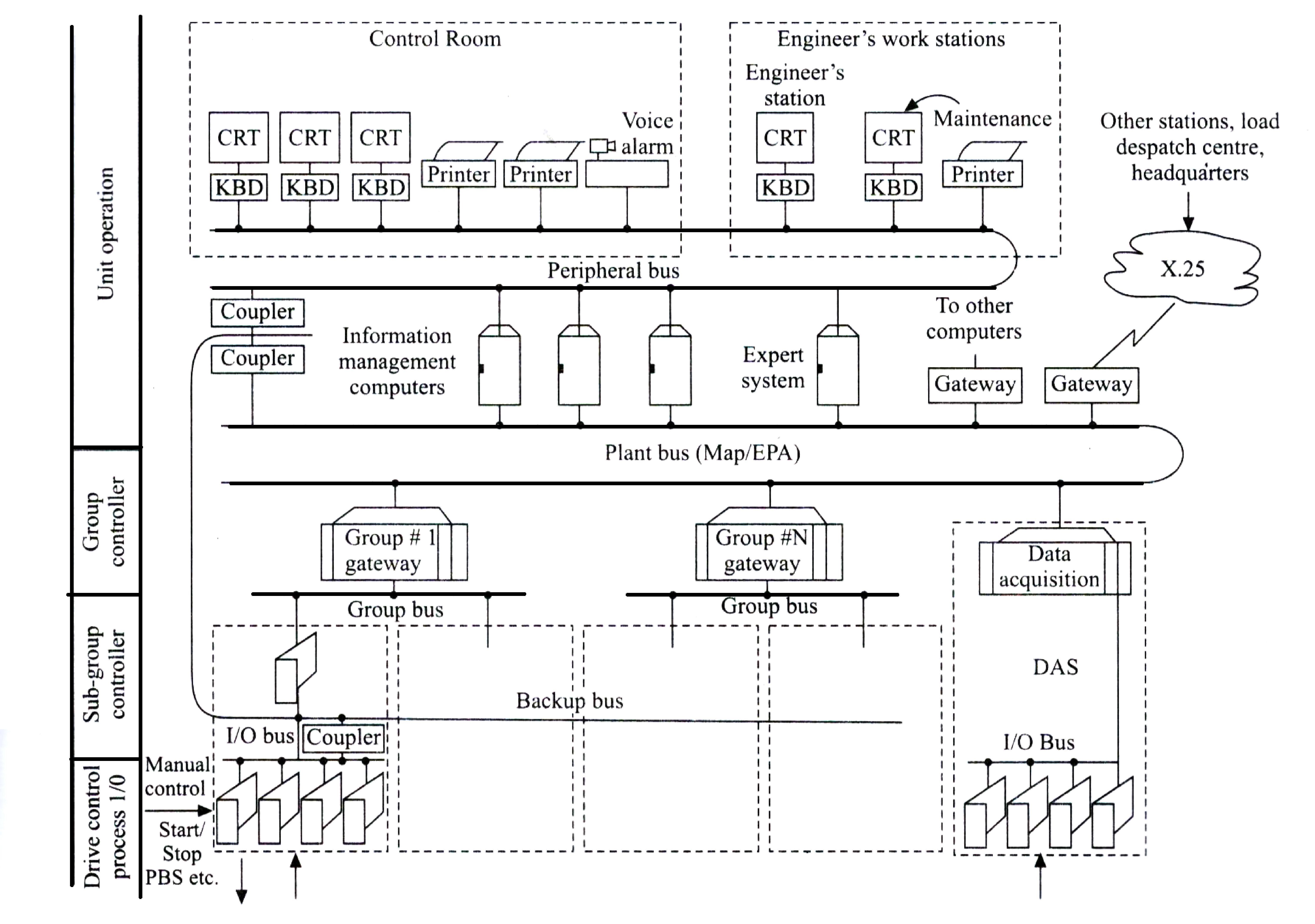
The hardware structure of DCS for power plants typically consists of
Field Station
- This consists of an Input unit, Output unit, and Drive control modules.
- These modules provide the interface of the process, including push buttons, indicators, and drives.
- The protection logic is included in the drive control modules to ensure plant equipment safety
- This logic can be implemented by Erasable Programmable Logic Devices (EPLDS).
Typically, these modules are characterized by:
- Built-in microprocessor-based intelligence,
- Signal conditioning was performed,
- Built-in basic protection using EPLDs,
- Programmable fail-safe output conditions.
- Direct manual intervention at drive levels,
- Plug-in interface for serial I/O bus for greater reliability.
- Modulating and binary control was performed under the control of the sub-group controller.
Sub Group Controller Station
This station consists of a high-performance micro-computer module with a direct interface to the serial I/O bus and the higher-level group bus.
Group Controller Station
- This station provides the control of each plant sub-process and coordinates the control of individual equipment groups.
- These group controllers are interconnected via the plant bus to exchange data among themselves and with the high-level controllers.
- The group controllers are equipped with high-performance microprocessors with necessary memory modules.
Unit Level Control
- This station consists of display and keyboards, supported by hard copy units.
- A host of plant data has to be evaluated, sorted, further processed, and assigned to the various display units or printers for logging.
- The color CRTS are used as part of low-cost PCs with the necessary display functions.
- Unit-level computers (ULC) send all required dynamic data to reduce the processing overhead.
- The number of CRT workstations depends upon the control philosophy to be employed for a particular plant.
- The number of unit-level computers depends upon the extent of functions required to be performed.
- A manual control station facilitates the operation of final control elements bypassing all the above control stations.
The unit-level computers perform the following functions.
- Plant Automation
- Control Operation
- Alarm and Display Control
- Calculations, logs for historical recording
- Software development.
- Database management.
The Plant Bus
- This bus runs throughout the power plant to connect all sub-group control stations and level stations.
- The plant bus is a map-type system that can integrate other computers and systems.
- The plant bus updates the plant database through the lower level buses which are maintained at the unit level.
- The plant bus transmits unit operation commands to the lower level controller.
The Bus System
- The I/O bus system hierarchically is an organized bus system for the DCS architecture of the power plant is usually at the lowest level and connects the I/O and drive cards of a particular sub-group.
- This is a short-distance bus, generally confined within the cabinet, which houses a sub-group controller.
- The I/O bus is controlled by the sub-group controller and it should have a short time response to plant conditions.
- The I/O modules are intelligent only status or other significant changes need to be reported over the bus to reduce bus speed considerations by using RS 485 connection type.
The Group Bus
- This bus connects all sub-group controller stations and the pertaining group controller station.
- This bus enables the group controller to perform the overall control coordination for a group.
The Peripheral Bus
This bus connects all the CRTS, keyboards, printers, and video copiers, required for the operation and monitoring of the plant.
The Backup Bus
- This bus provides a direct connection from the I/O bus to the plant bus.
- Here the CRT or keyboard of the plant operates in case of any failure at the group and subgroup levels
- If intelligent sensors and actuators are introduced, the need for many of the I/O and drive cards can be dispensed with. It would then be necessary to link these devices with a Fieldbus.
Software of DCS in Power Plant
The software system of the DCS includes a wide range of functions to meet the power plant requirements.
Such as
Data Acquisition and Alarming
- The system acquires the process signals of various scan rates, for performing input conditioning and calculations.
- Alarms on inputs or calculated variables can be generated on fixed or variable limits, with the provision for alarm suppression schemes.
Data Logging
- For assigning several printers at the unit level for logging functions.
- It can select any printer for any type of log that can be initiated on demand times.
- The logs and formats are configurable.
The logs of importance are:
- Periodic logs: Log reports for hourly, daily, monthly, or predetermined time intervals like for turbine run or boiler start-up.
- Event Logs: Log report for alarms, sequence of events, operator actions, and hardware faults.
- Demand logs such as operator-requested log printouts like shutdown trip analysis logs, maintenance logs, and performance logs.
Performance Calculations
- The capability of high-level programming language enables easy performance calculations.
- Based on average record data these can be initiated on each scan cycle periodically.
Control Functions
- These are distributed to various DCS controllers so that each controller can store the configured functions from the unit level out of a set of standard algorithms.
- The unit level computers (ULCs) supervise the plant status and send the target values to the lower level controllers.
Human Interface System of DCS application
- The DCS provides CRT-based man-machine communication.
- This includes the features like keyboards and light pens for plant operation.
Features of the Human Interface System are:
Alarm Display
- Easy to understand group display of alarm occurrences in chronological order.
- Scrolling of the display as new alarms come.
- Color change and flashing sequences to indicate alarm status.
Mimic Display
- Display of a mimic diagram from a predefined library.
- Plant control from the mimic display.
- Zooming into a detailed mimic diagram from an overview mimic displays a target mimic. Such as point details, and emergency details.
Trend Display
- Eight-point trend curve display.
- Detailed information on trended parameters.
- Exact value/status readout through cursor positioning on curves.
- Real-time or historical trend display.
Bar Chart Display
- Vertical bars represent values of variables
- Alarm limit indication on bar
- Color changes of the bar on the alarm
- Operating parameters displayed alongside bars
- CRT/keyboard operation from bar chart display
Operator Guidance Messages
Special operator guidance display
Multi Format Display
- Superimposition of mimics, trends, and bar charts
- Window displays
Plant Automation Messages
- Missing criteria display
- Step execution description
- Breakpoint messages.
Voice Alarm Annunciation
- In addition to alarm reporting through CRTs and printouts,
- The system provides audio alarm annunciation through a synthesized alarm message which can repeatedly output through a speaker or buzzer till it is acknowledged by the operator.
The advantages of the voice output alarm are:
- Fast operator response to alarm
- More plant people are aware of the alarm.
- Simultaneously the alarm message, depending on priority, can be directed to various levels of plant personnel situated in various areas of the plant.
- If necessary the voice alarms can be synthesized in local languages.