Thermodynamic laws are fundamental truths based on energy exchanges between a system and its surroundings.
The first law of thermodynamics states that energy cannot be created or destroyed, but only be converted from one state to another.
Energy is referred to as Work done, Heat, and Internal energy.
Work done is defined as a force that acts through a distance and the transfer of energy from the system to its surroundings results.
Heat is defined as an energy transfer that occurs between two regions of different temperatures connected by a thermal conductor.
Internal energy is the energy stored in a body, it is equal to the heat flow into the system minus the work done by the system on its surroundings.
The second law of thermodynamics states that heat flows from regions of high temperatures to regions of low temperatures.
From both laws, the energy is constantly degraded in a thermodynamic process there is always less energy available for doing work.
This leads to the definition of entropy which always increases as energy becomes less available for doing work.
A thermodynamic cycle is a series of thermodynamic processes for transferring heat and work, in varying pressure, temperature, and other variables returning to its initial position eventually.
The first law of thermodynamics explains that the net heat input is equal to the total work output over any cycle.
Thermodynamic cycles often use quasistatic processes to define the operation of actual devices.
If the cyclic process operates in a clockwise direction around the loop, then it represents a heat engine, hence W will be positive.
If the cyclic process operates in the counterclockwise direction around the loop, then it represents a heat pump, hence W will be negative.
Thermodynamic Cycle
A Thermodynamic cycle consists of four phases.
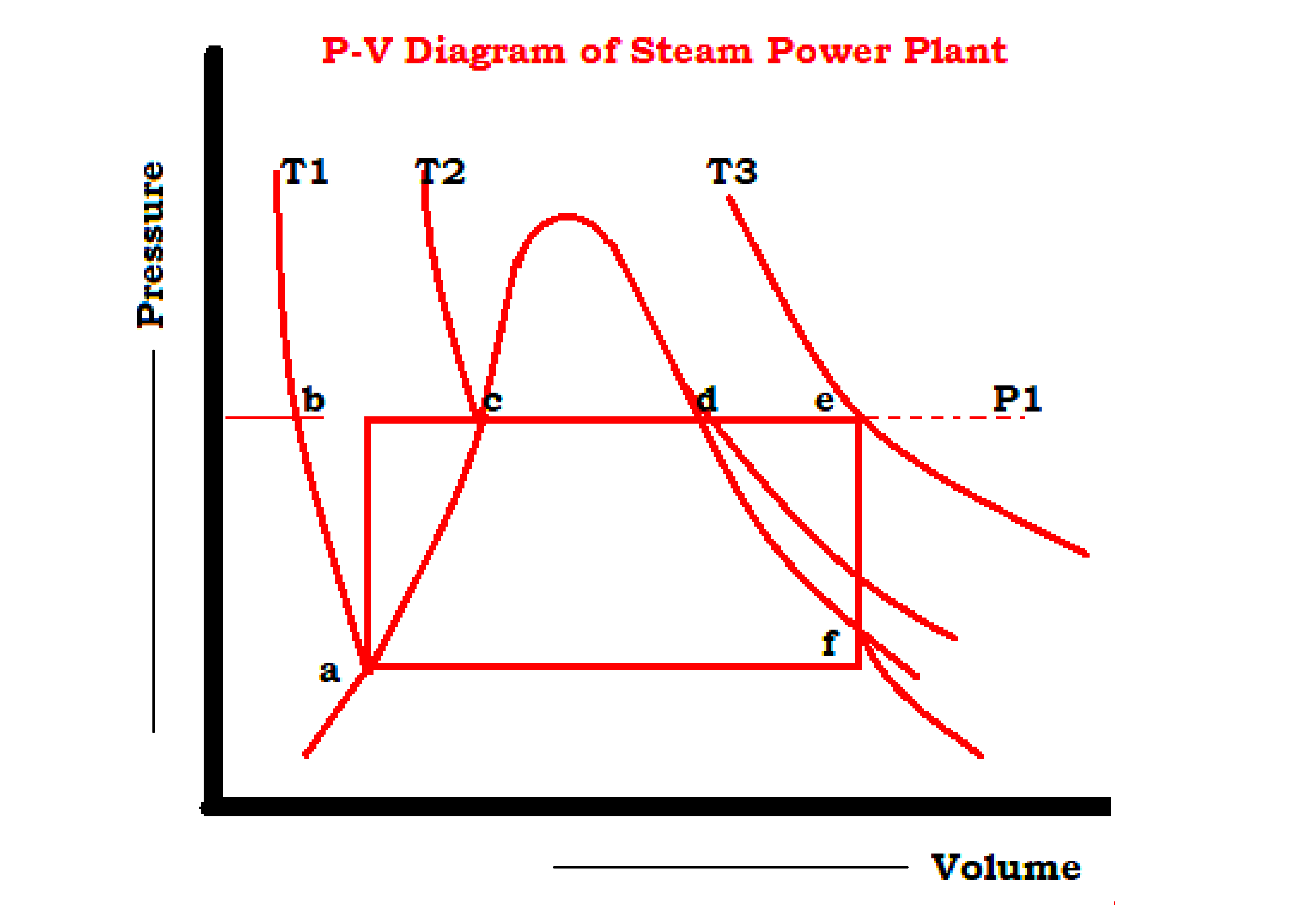
- Heat addition bcde in a boiler at constant pressure P1 changing the water at b to superheated steam at e.
- Isentropic expansion ef in a prime mover from initial pressure P1 to backpressure P2.
- Heat rejection fa in a condenser at constant pressure P2 with wet steam at f converted to saturated liquid at a, and
- Isentropic compression ab of water in a feed pump from pressure P1 to pressure P1.
Two primary classes of thermodynamic cycles are
- Power cycles: converts some heat input into mechanical work.
- Heat pump cycles: transfers heat from low to high temperatures using mechanical work input.
- A quasistatic processes cycle operates as a power or heat pump cycle by controlling the process direction.
- On a Pressure-Volume diagram or Temperature Entropy diagram, the clockwise and counterclockwise directions indicate power and heat pump cycles, respectively.
- The thermodynamic power cycle is the base for heat engine operation which supplies most of the world’s electric power to run motor vehicles.
- Based on the type of heat engine, the thermodynamic power cycle is classified as
- The most common thermodynamic power cycles that represent internal combustion engines are
Rankine Cycle
The Rankine cycle is a type of thermodynamic cycle used in many power stations to generate electricity.
The Rankine cycle is the real-world approach to the Carnot cycle.
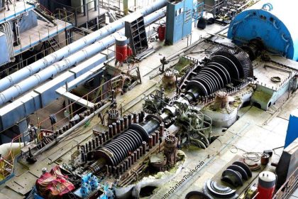
Superheated steam generated in a boiler is expanded into the steam turbine.
The steam turbine drives a generator, to convert the work into electricity.
The power plant generates electric power by using fuels like bagasse, coal, oil, or natural gas.
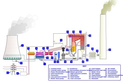
Generally, a Power plant consists of a Boiler, Turbine, Condenser, and Feed pump.
Fuel is burned in the boiler furnace and the superheater heats the water to generate steam.
The steam is further heated to a superheated state in the superheater.
This pressurized steam is used to rotate the steam turbine which powers the generator.
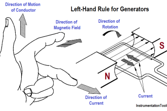
Electrical energy is generated when the generator windings rotate in a strong magnetic field.
After the steam leaves the turbine it is cooled to its liquid state in the condenser.
The liquid is pressurized by the pump prior to going back to the boiler.
Rankine Cycle Process
The Rankine cycle is a heat engine with a vapor power cycle.
Here, water is used as a working fluid.
Typically, the Rankine cycle operates at a pressure between 0.06 bars and 50 bars.
The pump and turbine in an ideal Rankine cycle are isentropic. It means no entropy is generated in the pump and turbine, and hence work output is maximized.
The Rankine cycle consists of four states that are identified by number in the diagram to the right.
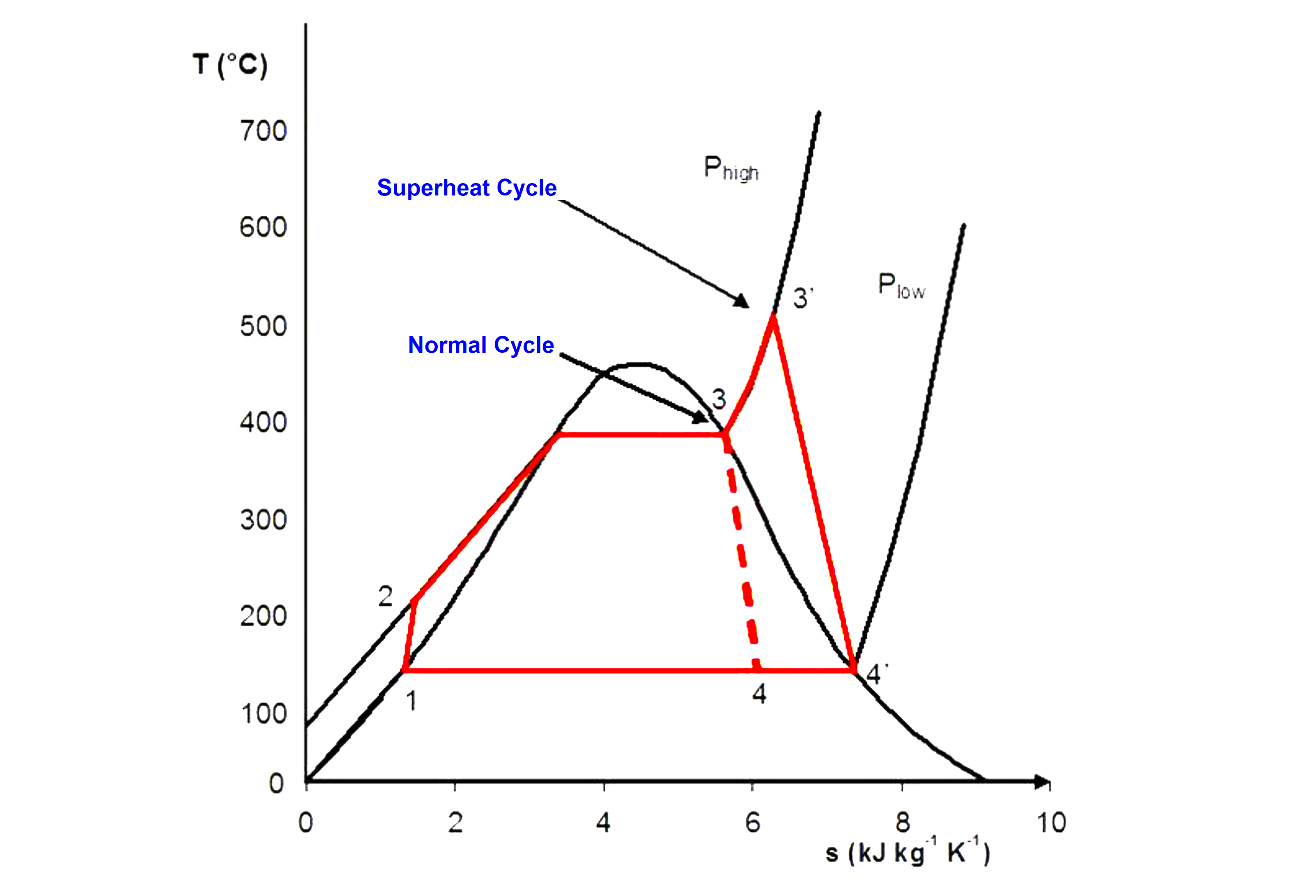
State 1-2: The liquid is used as a working fluid, pumped from low pressure to high pressure since the pump requires little input energy.
State 2-3: The high-pressure liquid enters a boiler drum and is heated by an external heat source at constant pressure to become a dry saturated vapor.
State 3-4: The dry saturated vapor expands through a turbine, generating power. This decreases the temperature and pressure of the vapor, and some condensation may occur.
State 4-1: The wet vapor enters a condenser where it gets condensed at a constant pressure and temperature to become a saturated liquid. The pressure and temperature of the condenser are fixed by the temperature of the cooling coils as the fluid is undergoing a phase change.
Stages 1-2 and 3-4 are represented by vertical lines on the T-S diagram and resemble the Carnot cycle.
The Rankine cycle shown here prevents the vapor from ending up in the superheat region after the expansion in the turbine, which reduces the energy removed by the condensers.
The work output of the Steam turbine and the work input to the Pump are given by
Work Output =W1 = m (h1-h2)
Work Input = W2= m (h4-h3)
The Heat supplied Q1 to the boiler, & heat rejected Q2 from the condenser are
Q1 = m*(h1-h4)
Q2 = m*(h2-h3)
The total work output of the cycle is given by :
W total= W1 – W2
The Thermal Efficiency of a Rankine cycle is:
N thermal = W/Q1
The efficiency of the Rankine cycle is not as high as the Carnot cycle but the cycle has fewer practical difficulties and is more economic.
Regeneration helps improve the Rankine cycle efficiency by preheating the feed water into the boiler.
Regeneration can be achieved by open-feed water heaters or closed-feed water heaters.
In open-feed water heaters, a fraction of the steam exiting a high-pressure turbine is mixed with the feed water at the same pressure.
In a closed system, the bled from the turbine is not directly mixed with the feed water, and therefore, the two streams can be at different pressures.
Organic Rankine Cycle
“Organic” is a term used in chemistry to describe a class of chemicals that includes Freon and most of the other common refrigerants.
A Rankine cycle is a closed-circuit steam cycle.
An “organic” Rankine cycle uses a heated chemical instead of steam as found in the Rankine Cycle.
Chemicals used in the Organic Rankine Cycle include Freon, butane, propane, ammonia, and the new environmentally-friendly refrigerants.
Carnot Cycle
The Carnot Cycle has been described as being the most efficient thermal cycle possible, wherein there are no heat losses, and consists of four reversible processes, two isothermal and two adiabatic.
It has also been described as a cycle of expansion and compression of a reversible heat engine that works with no loss of heat.
By using the second law of thermodynamics it is possible to show that no heat in the engine can be more efficient than a reversible heat engine working between two fixed temperature limits.
This heat engine is known as the Carnot cycle and consists of the following processes
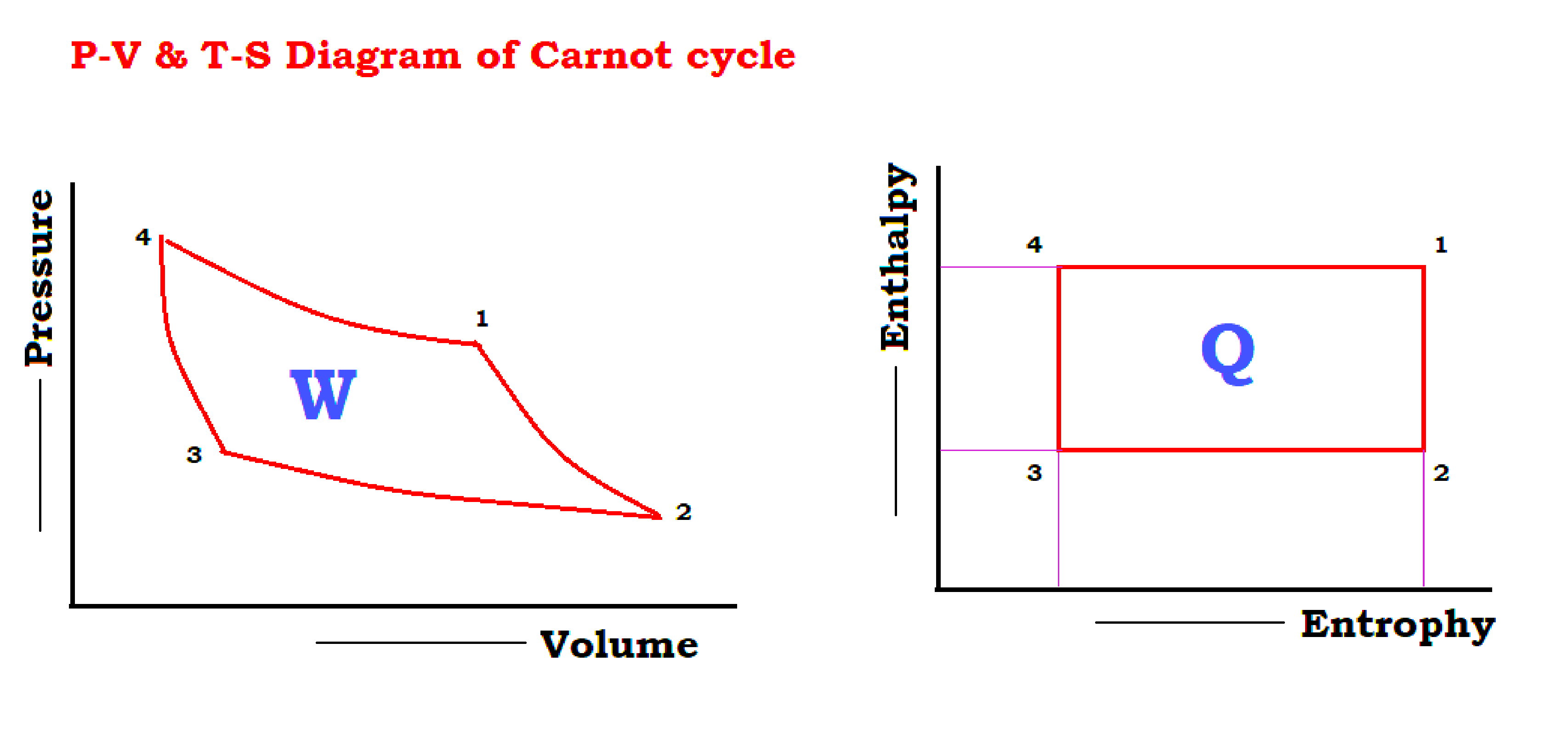
- 1 to 2 isentropic expansions
- 2 to 3 Isothermal heat rejection
- 3 to 4 isentropic compression
- 4 to 1 Isothermal heat supply
The Carnot cycle has a low work ratio. Although this cycle is the most efficient system for power generation theoretically, it cannot be used in practice.
There are several reasons such as low work ratio, economical aspects, and practical difficulties.
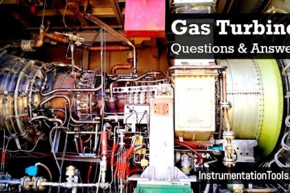
Brayton Cycle
- The Brayton cycle is a thermodynamic cycle that describes the workings of the gas turbine engine, the basis of the jet engine, and others.
- It is also sometimes known as the Joule cycle.
A Brayton-type engine consists of three components:
- A gas compressor.
- A mixing chamber.
- An expander
The Ideal Brayton cycle has
- Isentropic Process – Ambient air is drawn into the compressor, where it is pressurized.
- Isobaric Process – The compressed air then runs through a combustion chamber, where fuel is burned, heating that air-a a constant-pressure process, since the chamber is open to flow in and out.
- Isentropic Process – The heated, pressurized air then gives up its energy, expanding through a turbine (or series of turbines). Some of the work extracted by the turbine is used to drive the compressor.
- Isobaric Process – Heat Rejection (in the atmosphere).
The actual Brayton cycle has
- Adiabatic Process – Compression.
- Isobaric Process – Heat Addition.
- Adiabatic Process – Expansion.
- Isobaric Process – Heat Rejection.
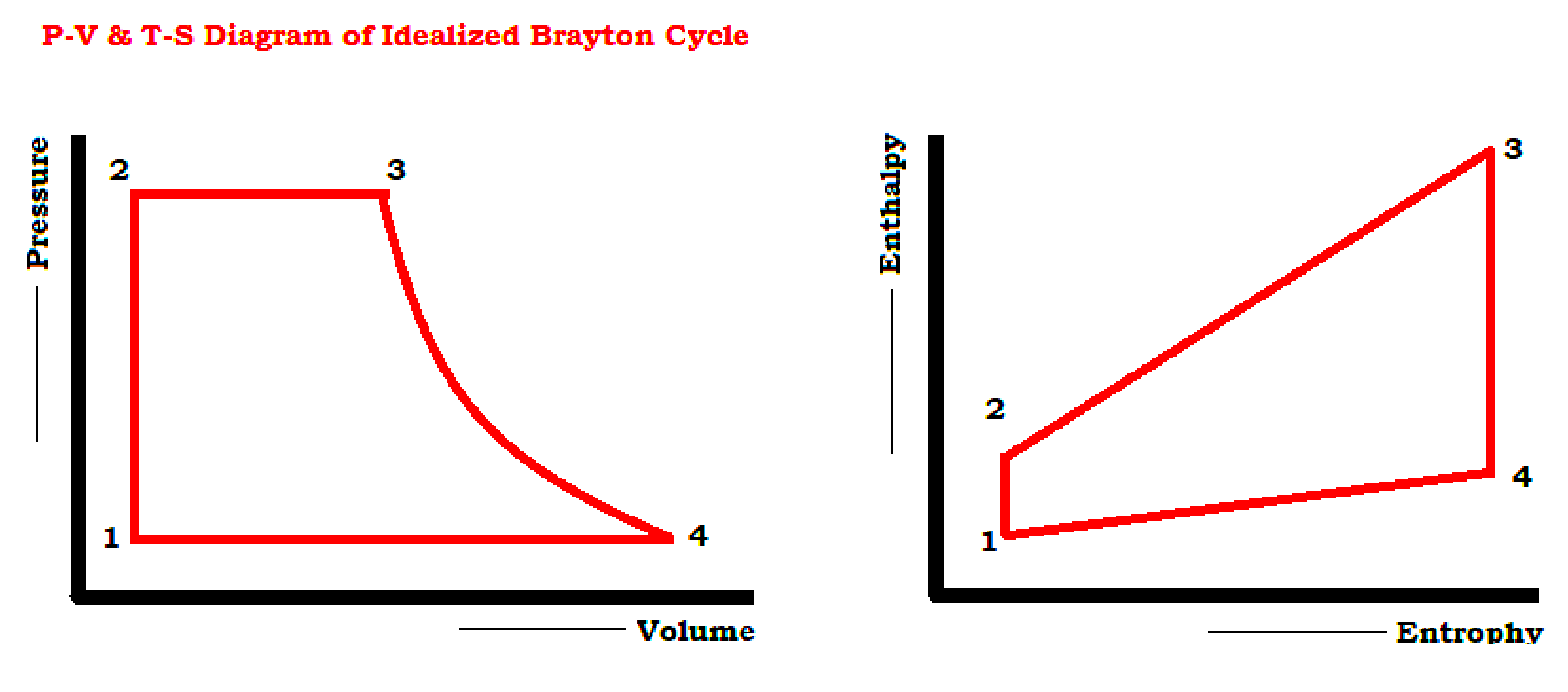
The four steps of the cycle are
- 1 to 2 Isentropic Compression
- 2 to 3 Reversible Constant Pressure Heat addition
- 3 to 4 Isentropic expansion
- 4 to 1 Reversible Constant Pressure Heat rejection.
The efficiency of the Brayton cycle can be improved by
- Intercooling
- Regeneration
- Combined cycle system to increase overall efficiency.
- The cogeneration system makes use of waste heat for heating feed water.