In this article, we will learn various Process and Mechanical Parameters in steam turbines related to water and steam.
Process Parameters
Some of the process parameters are steam pressure, steam temperature, steam flow, condenser level, condenser vacuum, etc.
Steam Pressure
- A pressure transmitter is provided to measure and transmit the steam inlet pressure signal to the control room.
- In addition, bourdon tube pressure gauges are installed to measure steam pressure at various points for local display for operator’s guidelines.
- Main steam pressure, steam pressure after inlet valves, stage steam pressures, and exhaust steam pressure are such points.
Steam Temperature
- The temperature transmitter is provided with the thermocouple, compensating leads, and cold junction compensation to measure the temperature of the inlet steam.
- In addition, steam temperatures after the inlet valve, stage, and exhaust temperatures are measured and locally displayed with the help of temperature gauges.
Steam Flow
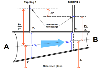
- Measurement of Inlet steam flow is done with an orifice head installed in the steam line.
- The differential head produced is measured using Differential Pressure Transmitter and square rooted to obtain linearized flow reading.
- The steam flow is also integrated for accounting and analysis purposes.
- Knowing the total steam consumed by a turbine for a specific period and the power generated for the same period, to analyze the performance of a steam turbine.
- Steam consumed per MW of power produced is called specific steam consumption.
- Turbine performance may be rated according to this factor among different turbines in the power plant.
Condenser Level
- A condenser is a unit where the exhaust steam from the turbine is condensed.
- It operates at a pressure lower than atmospheric pressure, i.e. vacuum.
- There are two objectives of using a condenser in a steam plant:
- To minimize the turbine exhaust pressure to maximize the specific output of the steam turbine.
- To recover high-quality feed water in the form of condensate, and to feed back to the steam generator without any further treatment. As a result, only the makeup water needs to be treated to replenish the water losses.
- The water level in the condenser vessel changes when the exhaust steam gets condensed.
- It is very important to know the condenser level from the operation point of view.
- Level measurement is continuously done on a pressurized vessel.
- The level switches are provided at different levels of the condenser for annunciation purposes.
Condenser Vacuum
- The vacuum created in the condenser helps to reduce the turbine exhaust pressure to increase the specific output of the turbine.
- If the temperature of circulating cooling water in a condenser is low, it creates a vacuum for the turbine.
- A condenser by lowering the backpressure to around 50 mmHg increases the plant efficiency and reduces the steam flow for a given output.
- Output and efficiency are high at lower pressure hence, it is important to measure the vacuum pressure created in the condenser.
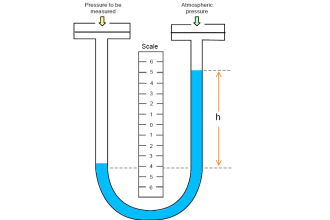
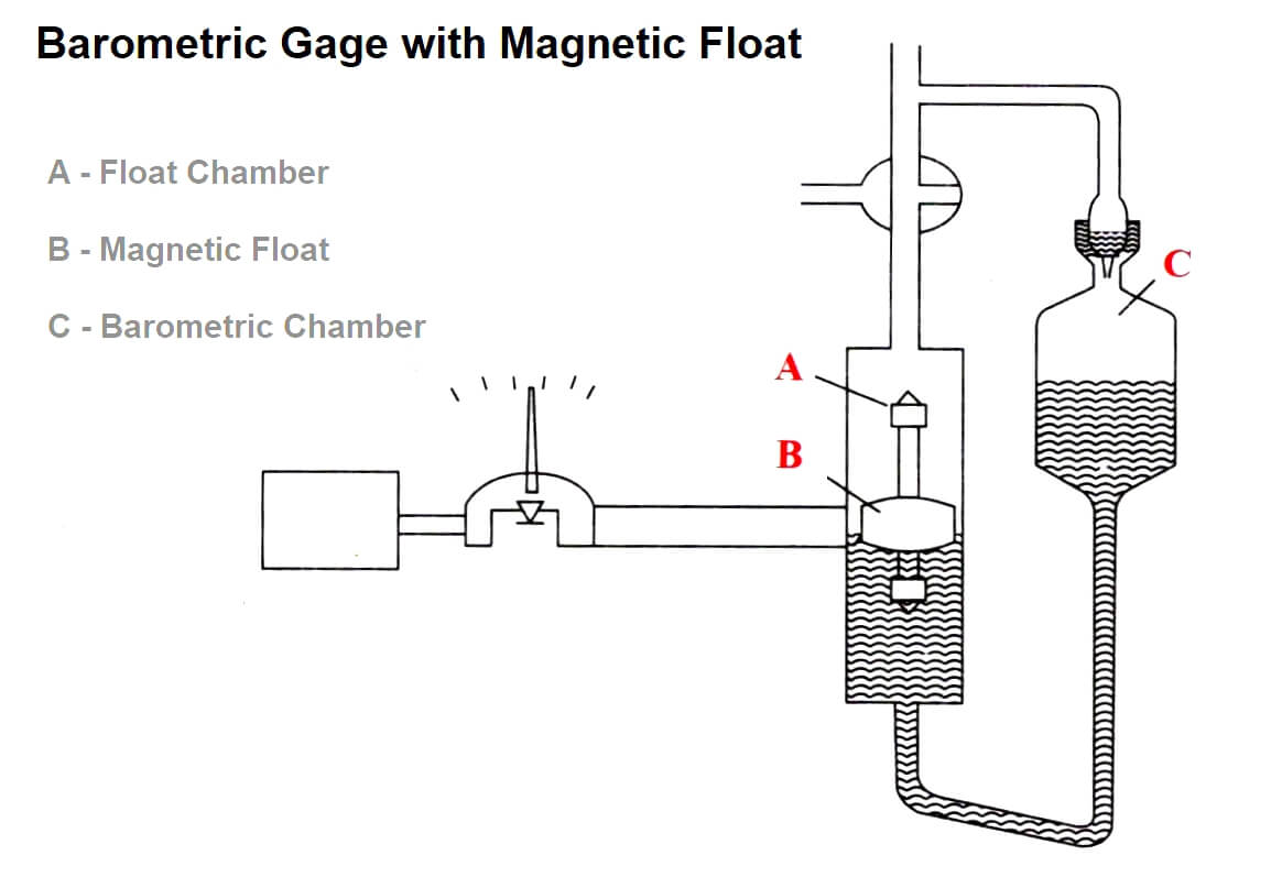
- A Torricelli vacuum of 0 mmHg is maintained in the space above the mercury in the barometric chamber.
- When the test pressure in the float chamber becomes equal to the vacuum then the mercury level in both chambers is the same.
- As the pressure in the float chamber rises, the mercury level in the float chamber is depressed.
- The float position is detected by a magnet, disturbing the float chamber.
- The range of vacuum in steam turbines is normally maintained at 0 to 200 mmHg.
- The three-way plug allows testing the unit for possible vacuum loss caused by evaporation from the mercury or vessel walls.
- The plug is opened to allow air to enter the float chamber, to force the mercury against the seal of the barometric chamber.
- Any traces of gases or vapors will be removed and drawn off by evacuation through the riser tube.
Mechanical Parameters
In this section, we deal with measurements related to mechanical equipment like turbine rotors, bearings, couplings, casing/shell, support systems, etc.
Speed
Turbine shaft speed is very important as the speed decides the frequency of the electrical power generated by the alternator coupled with the turbine.
We know that,
Frequency (F) = (N*P)/120
Where
P= Number of poles
N = Speed in rpm
F= Supply frequency in Hz
As the frequency is fixed at 50 Hz,
- For 2 pole machines [P=2]
N= 120*50/2
N= 3000 rpm
Hence, the generator speed is 3000 rpm
- But, for 4 pole machines [P=4]
N= 120*50/4
N= 1500 rpm
Hence, the generator speed is 1500 rpm
- From the point of consumers’ view, it is important to control the speed of the turbine to maintain the supply frequency.
- Hence the turbine speed is always measured and displayed in the control room.
- The speed signal is used in a speed control loop to maintain the turbine speed automatically.
- The measurement of generator frequency represents speed measurement.
- But in practice, analog or digital tacho-generator are used to measure the speed of the turbine shaft.
- Some speed measuring devices such as A.C. tacho-generator, D.C. tacho-generator, induction type speed sensor, and magnetic type speed sensor are also used.
- Contact-type tacho generators are directly coupled with the turbine shaft at the end.
- In the case of Non-contact type tacho generators, magnetic pulse-type sensors are employed.
- Tachometers are also possible to be employed.
- The output of the speedometers is always converted into a standard electrical signal (normally 4-20 mA D.C.) for indicating, recording, and controlling purposes.
Vibration & Displacement
- A stationary vibration monitoring system installed on turbines consists of accelerometers or proximity sensors fixed radially in each bearing at the end of the shaft or the thrust collar.
- Two sensors fixed at right angles to each other are used in bearings.
- Electronic monitoring equipment used measures the acceleration or displacement that occurs at each monitoring point.
- The monitoring equipment includes an ‘ALARM’ set to warn the operator of an impending problem, and a ‘TRIP’ set to shut down the machine.
- In many instances, a vibration-initiated shutdown can prevent major damage in situations in which, without prompt action, the equipment could be lost.
- The terms such as Displacement, velocity, acceleration, and vibration are interrelated with each other.
- Vibration can also be demonstrated in terms of displacement, velocity, or acceleration.
- If the sensor is fixed on the surface of the vibrating object, it generates absolute vibration relative to a fixed point in space.
- If the mass of the rotating object and resonant frequency affects the sensor attaching to it a small hole can be made through bearing housing and a non-contacting proximity probe that can easily sense the relative motion between shaft and bearing.
- The electronics linked with the sensor may be integral or remote.
- Commonly available sensors for vibration and displacement measurements are Relative Accelerometers, Absolute or Seismic Accelerometers, Variable Reluctance Accelerometers, Eddy Current Proximity Vibration Pick up & Mechanical-Magnetic Vibration Sensors.
Bearing Temperature
- Bearing temperature is an indication of the occurrence of lubrication in the bearing.
- It is also a way of detecting a failure in bearings prior to complete mechanical failure.
- Mechanical wear accelerates as a result of improper lubrication of mechanical stresses that cause the failure of the bearing component.
- In some cases, the bearing begins to vanish or disperse huge amounts of energy which results in heating.
- A sudden rise in bearing temperature is a symbol of incipient failure.
- But at this time, it is essential to halt the operation of the machine immediately when a failure in the bearing is detected.
- Some turbine designs provide a very small clearance between stationary parts and rotating parts.
- If the bearing is damaged, it means the total destruction of the machine.
- Platinum Resistance Temperature Detector Pt100 is fixed in the bearing casing to meet the outer ring of the bearing.
- The same arrangement is done for both turbine bearings and alternator bearings.
- The signals are transmitted with the help of RTD- mA transmitters for indication and recording in the control room.
- Parallel indicators are also furnished in the local panel for operator supervision.
- Near the bearings, mercury-in-glass thermometers are fixed for local indication.
- This measurement is most essential, annunciation contacts are generated from both local mercury in glass thermometers and RTDs.
- Generally, ‘ALARM’ & ‘TRIP’ contacts are produced and interlocked with other safety systems.
Lube Oil Parameters
- Lubrication oil is used to cool the turbine bearings and alternator bearings.
- Various process parameters such as flow, level, pressure, & temperature are measured in connection with lube oil
- Pressure measurement is carried out with the help of a pressure transmitter for remote indication and with a Bourdon tube pressure gauge for local indication.
- Flow measurement is done with an orifice along with a DP transmitter or rotameter.
- In the case of rotameter along with DP transmitter, the purpose serves for both local and remote indication.
- Temperature measurement is carried out with RTD as a sensor and a transmitter for remote indication and control.
- Mercury in glass thermometers or gas-filled thermometers is used for local indication purposes.
- DP transmitter serves for remote transmission, and gauge glass serves for the local indication for measurement of Lubrication oil tank level
- Annunciation contacts are generated with the help of remote indicators and/or local indicators.
Casing or Shell Temperatures
- The turbine casing or shell temperatures are another group of important turbine parameters.
- The casing is the stationery element that covers the rotor and holds the nozzles, blades, and diaphragms that are required to control the physical state and path of the expanding steam.
- It is required to measure inlet steam temperature and the differential temperature between steam and shell to escape excessive temperature differences within the turbine casings at the time of startup and shutting down.
- Quick starting and loading generate huge temperature gradients, and excessive thermal strains produce cracks in the turbine casing if it is too large.
- The casing temperatures are measured at 6 different regions.
- The holes are drilled to place J-type thermocouples.
- After the sensors are put in and extension cables (compensating leads) taken out, they are grouped together and recorded in a multipoint recorder so that the comparison between temperatures is easily possible.
If you liked this article, then please subscribe to our YouTube Channel for Electrical, Electronics, Instrumentation, PLC, and SCADA video tutorials.
You can also follow us on Facebook and Twitter to receive daily updates.
Read Next:
- Turbine and Compressor System
- Steam Circuits in Power Plants
- Furnace Draft Control System
- Turbine Steam Pressure Control
- Working Principle of Steam Ejector