One of the most important and confusing concepts in Bently Nevada is Normal AND vs True AND.
This is used in logic building.
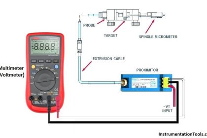
Suppose there is one heavy rating machine in your plant and obviously it is expensive. We use special safety systems for these machines like vibration and temperature monitoring and protection systems so whenever there is an abnormality in vibration/temperature observed, then the machine should trip accordingly.
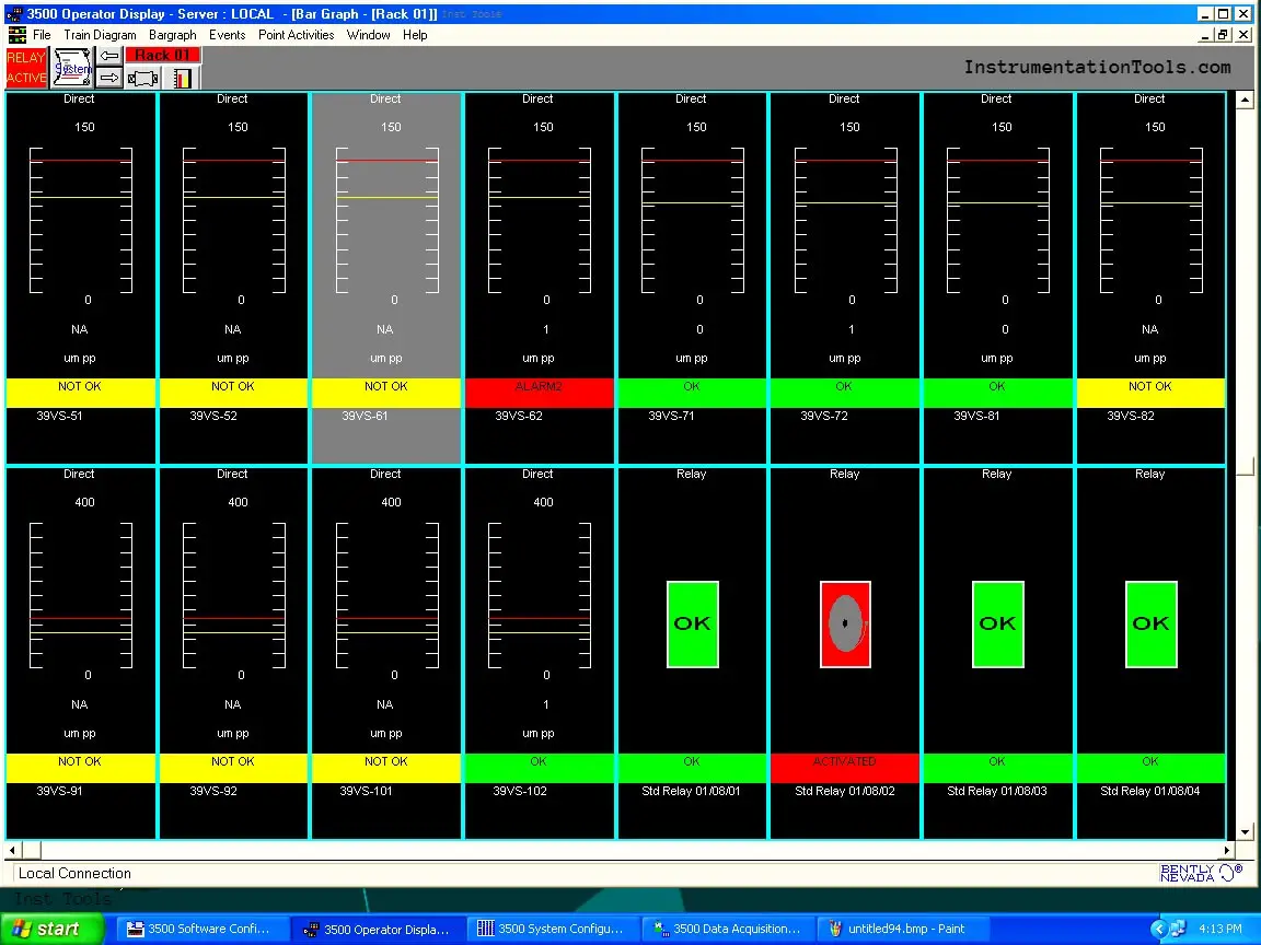
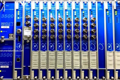
Bently Nevada Vibration System
Now assume the following logic:
High vibration in two vibration probes is used for machine trips. (The two probes must detect High vibration then only the machine will be tripped)
In the above case, what if 1 vibration probe goes to NOT OK? (NOT OK means the sensor probe failed or it is damaged). In this case, say only 1 probe detected it and as per logic, the machine should trip on high vibration of both probes, but the machine won’t trip because only 1 probe detected and the other probe is in a faulty state.
Now again think of another example where the process is more important and machines should not trip on spurious vibrations. Now here what if one vibration probe goes to NOT OK and the other detects high vibration?
Yes, it’s confusing!
Now here we have to understand the role of Normal AND and True AND.
Normal AND Logic
In Normal AND whenever a probe goes into the NOT OK state, it is taken out of logic, and logic is degraded.
Consider 2 out of 2 logic.
In the 2oo2 logic, if the Probe 1 detects high vibration and Probe 2 is NOT OK
Then logic becomes 1 out of 1 considering Probe 1 as input.
This type of configuration is used when the machine is more important than the process.
True AND Logic
In True AND whenever a probe goes into the NOT OK state, the logic remains the same.
Consider 2oo2 logic again.
In two-out-two logic, if Probe 1 detects high vibration and Probe 2 is NOT OK.
Then machine won’t trip even if Probe 1 detects high vibration.
This type of configuration is used when the process is more important than the machine.
This logic is driven through a relay which is normally de-energized (can be changed to normally energized also).
Normal AND Truth table
The below table shows the different possible scenarios using Normal AND logic in the Bently Nevada condition monitoring system.
| Vibration Probe 1 | Vibration Probe 2 | Relay Status |
| Normal Vibration | Normal Vibration | De-energized |
| Normal Vibration | NOT OK | De-energized |
| NOT OK | Normal Vibration | De-energized |
| High Vibration | NOT OK | Energized |
| NOT OK | High Vibration | Energized |
| NOT OK | NOT OK | De-energized |
| High Vibration | High Vibration | Energized |
True AND Truth table
The below table shows the different possible scenarios using True AND logic in the Bently Nevada condition monitoring system.
| Vibration Probe 1 | Vibration Probe 2 | Relay Status |
| Normal Vibration | Normal Vibration | De-energized |
| Normal Vibration | NOT OK | De-energized |
| NOT OK | Normal Vibration | De-energized |
| High Vibration | NOT OK | De-energized |
| NOT OK | High Vibration | De-energized |
| NOT OK | NOT OK | De-energized |
| High Vibration | High Vibration | Energized |
If you liked this article, then please subscribe to our YouTube Channel for Instrumentation, Electrical, PLC, and SCADA video tutorials.
You can also follow us on Facebook and Twitter to receive daily updates.
Read Next:


Thanks for the wonderful topic.
I just referred the documents of bently, i would like to give a correction that in the description above it is mentioned NOT OK means vibration is high; but as per bently documents, NOT OK means instrument failure. it may be Proximitor, Probe, Barrier if present, or The channel. please check once from your end and update.
Link for the document below.,
https://dam.bakerhughesds.com/m/113b4a288b90729d/original/GEA31971A-Centrifugal-Compress-App-Note_R4-pdf.pdf