Inst ToolsInst ToolsInst Tools
  • Courses
  • Automation
    • PLC
    • Control System
    • Safety System
    • Communication
    • Fire & Gas System
  • Instrumentation
    • Design
    • Pressure
    • Temperature
    • Flow
    • Level
    • Vibration
    • Analyzer
    • Control Valve
    • Switch
    • Calibration
    • Erection & Commissioning
  • Interview
    • Instrumentation
    • Electrical
    • Electronics
    • Practical
  • Q&A
    • Instrumentation
    • Control System
    • Electrical
    • Electronics
    • Analog Electronics
    • Digital Electronics
    • Power Electronics
    • Microprocessor
  • Request
Search
  • Books
  • Software
  • Projects
  • Process
  • Tools
  • Basics
  • Formula
  • Power Plant
  • Root Cause Analysis
  • Electrical Basics
  • Animation
  • Standards
  • 4-20 mA Course
  • Siemens PLC Course
Reading: Configuration of Profibus Network in Siemens PLC
Share
Notification Show More
Font ResizerAa
Inst ToolsInst Tools
Font ResizerAa
  • Courses
  • Design
  • PLC
  • Interview
  • Control System
Search
  • Courses
  • Automation
    • PLC
    • Control System
    • Safety System
    • Communication
    • Fire & Gas System
  • Instrumentation
    • Design
    • Pressure
    • Temperature
    • Flow
    • Level
    • Vibration
    • Analyzer
    • Control Valve
    • Switch
    • Calibration
    • Erection & Commissioning
  • Interview
    • Instrumentation
    • Electrical
    • Electronics
    • Practical
  • Q&A
    • Instrumentation
    • Control System
    • Electrical
    • Electronics
    • Analog Electronics
    • Digital Electronics
    • Power Electronics
    • Microprocessor
  • Request
Follow US
All rights reserved. Reproduction in whole or in part without written permission is prohibited.
Inst Tools > Blog > PLC Tutorials > Configuration of Profibus Network in Siemens PLC

Configuration of Profibus Network in Siemens PLC

Last updated: March 4, 2021 12:21 pm
Editorial Staff
PLC Tutorials
1 Comment
Share
5 Min Read
SHARE

In this article, I will cover the configuration steps of the Profibus network using Siemens Simatic manager.

Profibus is a famous communication protocol founded by siemens provide a baud rate of 187.5 kb/sec. We can connect up to 64 devices on a single network.

Also Read: Principle of Profibus

When I/O devices are installed over long distances instead to lay a cable from the control room to field can become complex and increase installation cost too.

To mitigate complexity, we can mount a small local panel near to field devices. Now the local panel will be connected to the control room system cabinets. We have to use IM (Interface Module) which will provide communication from that panel to control room utilizing Profibus method. This is called remote I/O.

It recognizes by its purple color outer jacket.

Configuration of Profibus Network

Consider that We have to mount some digital and analog devices on remote location. Let’s follow the below steps to configure the Profibus network.

Step 1:

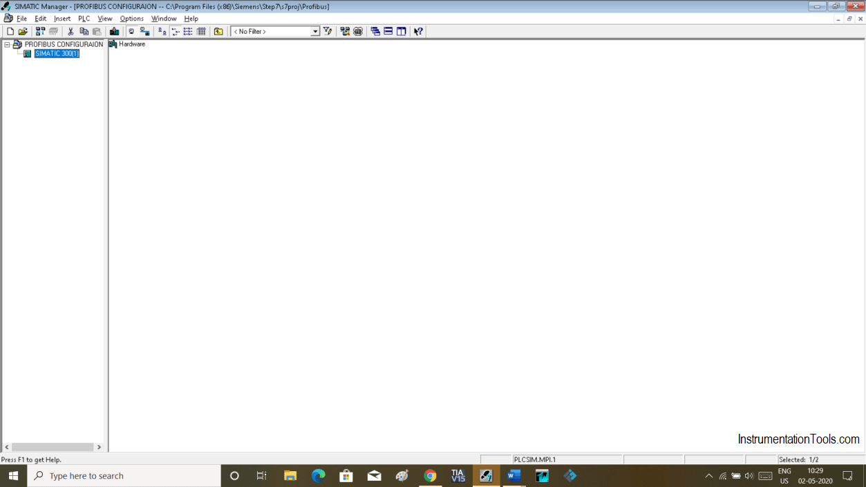
Open Simatic manager. Create a new project and select the type of the CPU.

Open Simatic manager

Step 2:

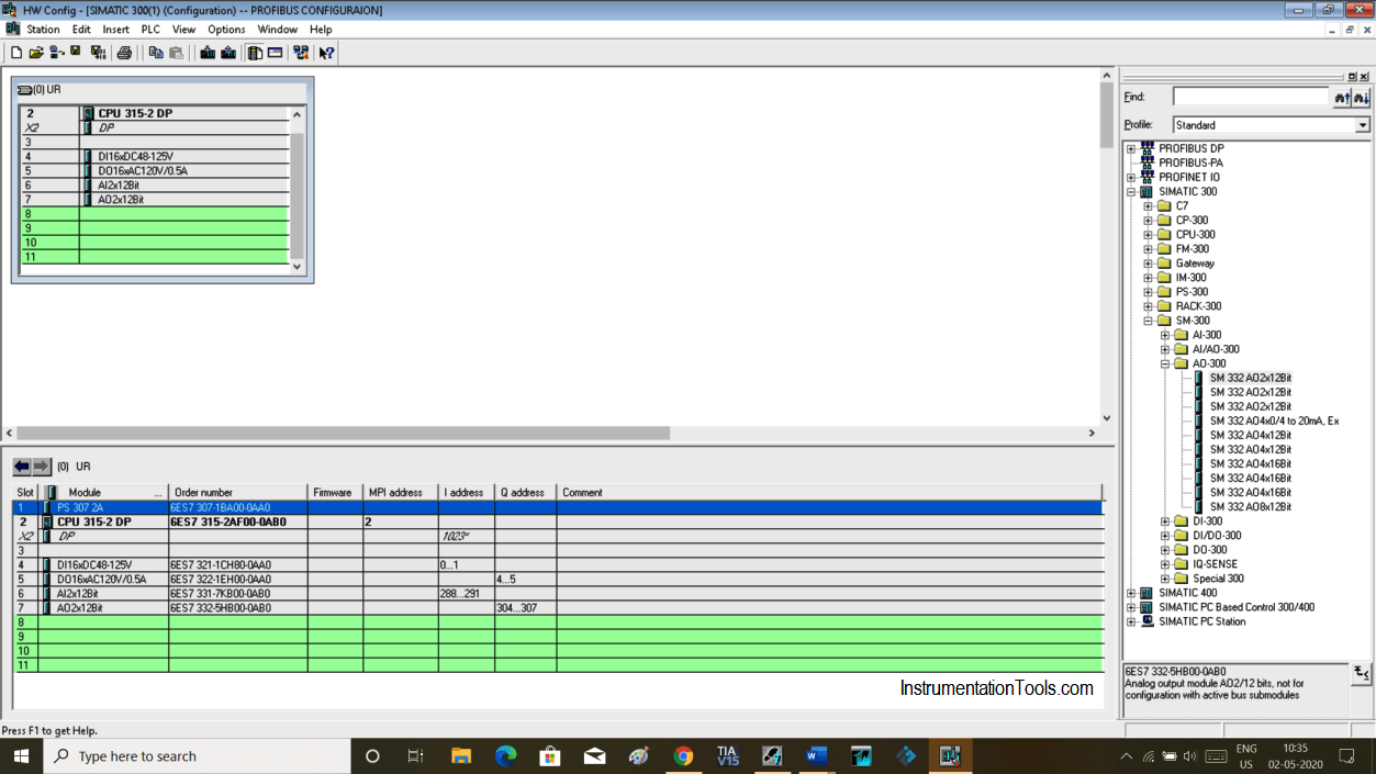
Select and add Required module as located in the main control room. Please visit my previous article on how to create a new project.

Select CPU type which has a Profibus port on it as we are going to configure the Profibus network. In our case, I have chosen CPU 315-2DP.

For the practical purpose you can choose random I/O otherwise choose as per your physical I/O arrangement.

Simatic Hardware Configuration

Step 3:

To create a Profibus network double click on “DP” as shown in the below window.

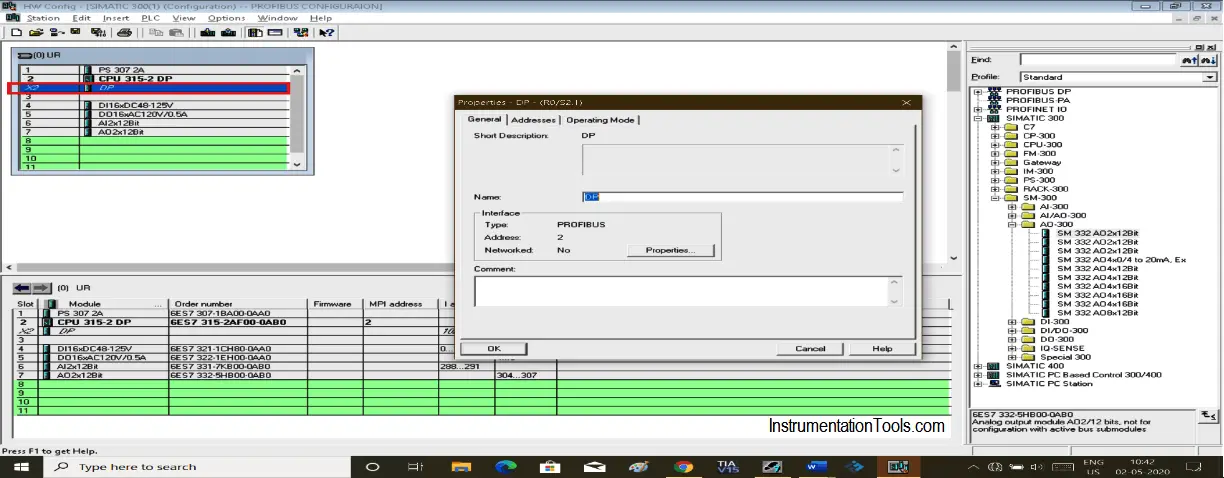
Clicking on DP will open a new pop-up window as shown in the below window.

create a Profibus network

Step 4:

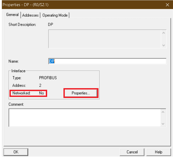
Here, “Networked selection is no”. To configure network click on “properties”.
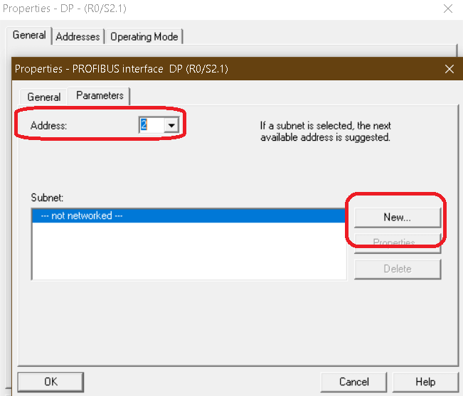
Siemens Networked selection

Step 5:

Clicking on properties will open up the following window. Click on “New” to add network. Here default address is “2”. Leave as it is.
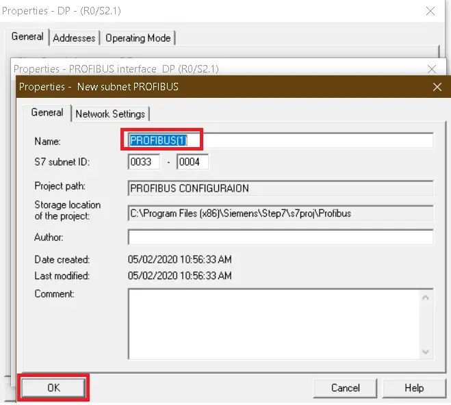
Profibus Interface Addresses

Step 6:

Clicking on new will pop up one more window. Change the name if you wish to. Click “ok” to add.
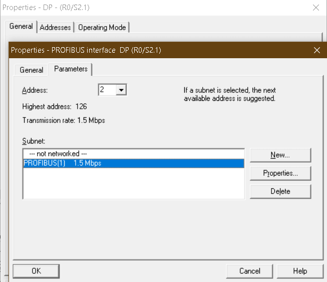
Profibus Network Settings

Step 7:

The network is added with default speed. Hit “ok” again to proceed.
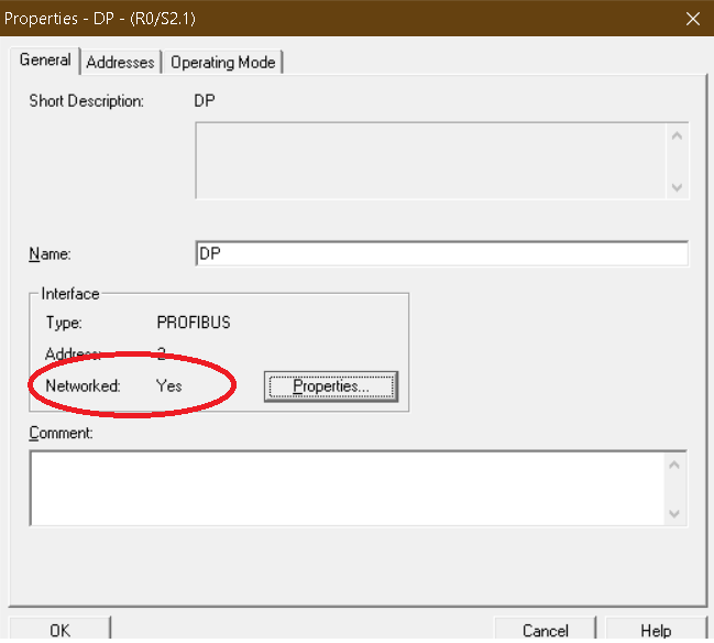
Profibus Interface DP

Step 8:

Here, previously “NO” is turned to “Yes”. Hit “ok” to proceed.
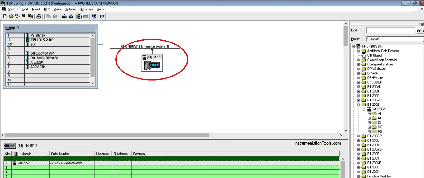
Profibus Window in Siemens PLC

Step 9:

Now you can see that the Profibus network is added. Here on this network, you can add Drive, IM, etc. We have to add here remote I/O, so we will configure Interface Module.
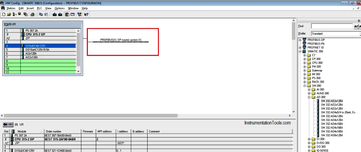
Profibus DP Master System

Step 10:

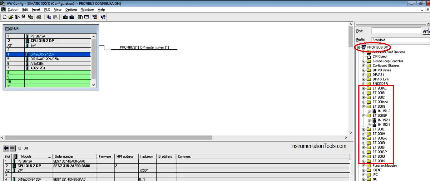
To add the Interface module we have to select ET (Electronic terminal). To add, expand “PROFIBUS-DP” where you can find a variety of “ET-200”.

To select the “IM” expand the “ET-200” module and select the Interface Module as per model number we have in the hardware.

For the sake of our example, I will use ET-200S.

Profibus Interface Module

Step 11:

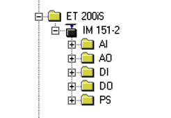
Here, expanding ET-200is will open IM 151-2. Add Analog and digital module as per model number located on the hardware.

ET 200 iS

Step 12:

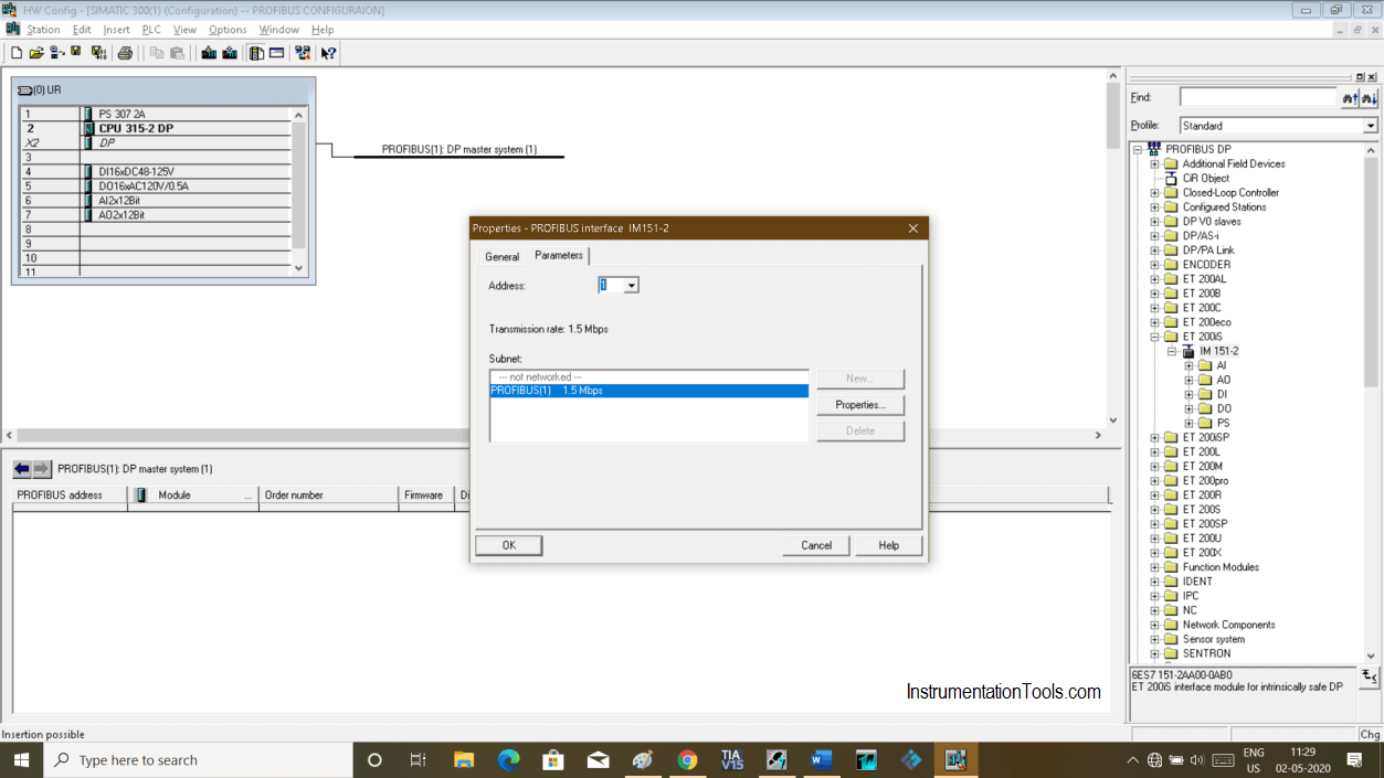
Drag and drop IM 151-2 on the network which we have created earlier.

The following window will pop-up asking you for the address. To Add address have a look onto actual IM where you can find DIP switches. See which DIP switches are on and add them.

For example, if ON DIP switches are 2, 4, and 8. Now add them 2+4+8 = 14. So. An address which we have to add here is 14.

The maximum address you can add is “128”.

After adding address hit “ok” to proceed.
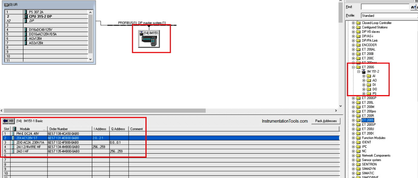
How to Configure Profibus in Siemens PLC

Step 13:

IM is added with the address which we had entered. Let’s add the I/O module.

Simatic 300 Profibus

Step 14:

Select IM to add modules. You can see below the window that I have added all the required modules installed in hardware as per the order number. We are done with Profibus Network.

Siemens Communication Settings

Author: Suhel Patel

If you liked this article, then please subscribe to our YouTube Channel for PLC and SCADA video tutorials.

You can also follow us on Facebook and Twitter to receive daily updates.

Read Next:

  • Siemens S7 1200 PLC configuration
  • Password Protect HMI in TIA Portal
  • Upload Siemens PLC Program
  • Backup from Siemens S7-300
  • Temperature Alarms in TIA Portal
Don't Miss Our Updates
Be the first to get exclusive content straight to your email.
We promise not to spam you. You can unsubscribe at any time.
Invalid email address
You've successfully subscribed !

Continue Reading

Why 24 Volts DC Power Supply is used? – Industrial Automation Systems
PLC based Gas Detection System using Ladder Logic Project
PLC to Start or Stop 3 Machines using 1 Switch Program
Create PLC Program based on Logic Circuit
Muting Functions of Safety Control Circuits – PLC Example
Machine Indicator Lights: PLC Programming Solution
Share This Article
Facebook Whatsapp Whatsapp LinkedIn Copy Link
Share
1 Comment
  • segwabanyana Wetshootsile says:
    May 5, 2020 at 9:57 am

    Please send me steps on how configure Variable Speed Drive (VSD) to control the speed of a motor.

    Reply

Leave a Reply Cancel reply

Your email address will not be published. Required fields are marked *

Stay Connected

128.3kFollowersLike
69.1kFollowersFollow
210kSubscribersSubscribe
38kFollowersFollow

Categories

Explore More

What is Seal-in Circuit ?
PLC Pneumatic Circuit Control
Operator Interface for SCADA System
Timer during Motor Direction Change PLC Program
PLC Mixing Logic in Liquids on EcoStruxure Machine Expert-Basic
Free Industrial Control System (ICS) Cyber Security Training Course
How to import GSD files into the TIA Portal? – Siemens PLC
PLC Program for Solenoid, Pilot Lamp, and Switch with Alarm

Keep Learning

PLC Example on Switch Program with Timers

PLC Example on Switch Program with Timers

PLC Program for Conditional Control Logic

PLC Program for Conditional Control Logic

Ladder Diagram Example using Memory Bits and Set Coils

Ladder Diagram Example using Memory Bits and Set Coils

PLC Logic Example on Multiple Switches and Motors

PLC Logic Example on Multiple Switches and Motors

Automatic exhaust fan control

XG5000 PLC Programming for Automatic Exhaust Fan

PLC Programming for Automated Curtain Control

Automatic Curtain Control – PLC Programming Solution

PLC Program for Fish Feeding System

PLC Program for Fish Feeding System

Download Free HMI software – CODESYS

Learn More

Components of SCADA

Components of SCADA

Ziegler-Nichols closed-loop Tuning

Ziegler-Nichols Closed-Loop Method (Ultimate Gain)

electromechanical-level-measurement-working-principle

ElectroMechanical Level Measurement Working Principle

ESP8266 WiFi Module Projects

ESP8266 WiFi Module Projects for Engineering Students

Siemens CPU MP Port

Siemens S7-300 CPU Suffix Explanation

IP transducer

Pilot Valves and Pneumatic Amplifying Relays

Allen-Bradley MicroLogix PLC Wiring

Programmable Logic Controller (PLC) Questions and Answers – 8

Switches, Repeaters, Bridges, Routers, Firewalls

Switches, Repeaters, Bridges, Routers, Firewalls

Menu

  • About
  • Privacy Policy
  • Copyright

Quick Links

  • Learn PLC
  • Helping Hand
  • Part Time Job

YouTube Subscribe

Follow US
All rights reserved. Reproduction in whole or in part without written permission is prohibited.
Welcome Back!

Sign in to your account

Username or Email Address
Password

Lost your password?