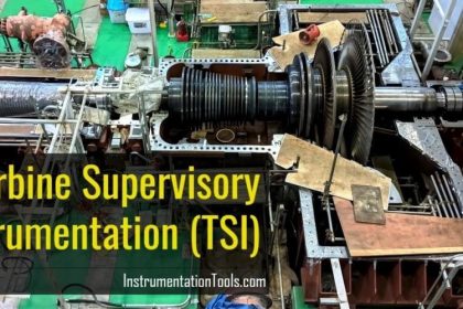
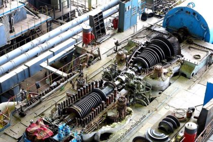
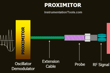
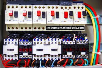
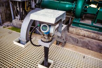
Turbine and Compressor Control System comprises of Electronic Governor Control System for Steam Turbine and Anti-surge Control System for Air compressor, Lubrication Oil Control System, Hot well, Seal oil control, Over Speed protection System and Vibration Monitoring System.
Turbine and Compressor Control System
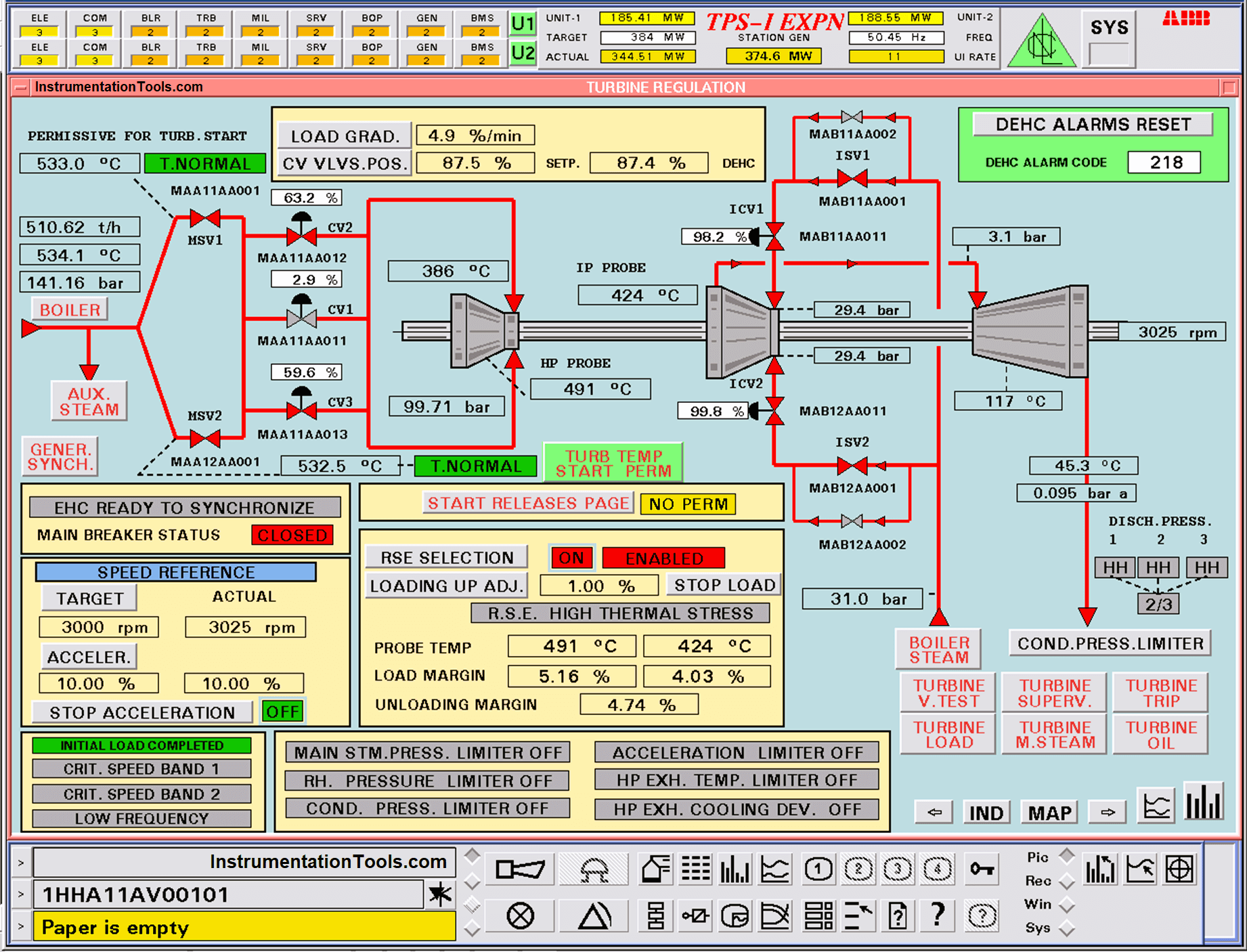
In a steam turbine, we need to maintain its speed constant during the normal operation against the continuous load change.
To achieve this, the system is designed to control the Pneumatic Control valve to control the speed over the full operational range from barring speed to over speed trip point and control of load around the rated speed after synchronizing.
The system also provides control on Surge of Compressor operations. Anti-surge protection does open a quick Exhaust Anti-surge Valve within a maximum of 500 msec.
The steam turbine is equipped with an electro-pneumatic speed governing system capable of controlling and regulating the speed of the steam turbine in conformity with performance Characteristics specified. It is included necessary speed, load, pressure, frequency controllers, steam valve operating device, etc.
The control system is microprocessor-based, protected against cyber security by suitable antivirus or firewall application, dual redundant is considered at all applicable levels as a minimum to ensure system availability and reliability.
The system has the facility to indicate the status of redundancy and switch over messages from dual to single mode. It must be possible to interface this status to DCS via a soft link. It has the facility to generate the “First Out” alarm in the case where a group of parameters is likely to trip the system.
In a redundant communication system, on the failure of the device or component, the redundant device shall take over automatically without interrupting the system operation.
In redundancy systems, we can do a manual switchover between the main system and standby system without disturbing the plant operations.
The system has capabilities to perform the calibration of governor control when a machine is under Shutdown. It is possible to adjust minimum & maximum stops and to manually stroke the Output of the actuator and valves from 0 to 100%.
During normal operation it is possible to view and adjust the following parameters to run the turbine:
- Turbine shutdown mode
- Turbine Ready to Start
- Turbine Startup
- Acceleration
- Run mode
- Over speed trip & test
The controller automatically adjusts the energy entering into the steam turbine in order to prevent its speed and output from fluctuating continuously even in case of a change in load condition.
Governor and steam control valve unit shall not increase the turbine speed to the turbine tripping speed even if the rated output is thrown off instantaneously.
On detection of the surge, the anti-surge valve must immediately open by a fixed amount above the current position demand.
The surge cycles must be broken during surge detection irrespective of the method used for surge detection or irrespective of the pattern of surge detected.
During the closing phase of the Surge Recovery response, the anti-surge valve should not be allowed to close back more than its position at the surge event to prevent reentering the surge zone (repeated surge).
Once process conditions are stabilized the operator can reset and the valve will close normally until either the surge control line is reached or fully closed. It shall be possible to initiate an alarm or a shutdown based on the number of detected surges within configured time.
If enabled, the anti-surge valve can be set to a fully open position if a consecutive surge alarm is detected. In the event of compressor suction pressure falling too low, the antisurge controller shall limit the minimum suction pressure by adjusting the opening of the anti-surge valve.
The minimum suction pressure value shall be a preset value. In the event of compressor discharge pressure rising too high, the antisurge controller shall limit the maximum discharge pressure by adjusting the opening of the anti-surge valve. The maximum suction pressure value shall be a preset value.
Vibration Monitoring System
The Machine Vibration Monitoring System also provides a critical analysis of the health of rotating machines and by using this data the plant maintenance personnel shall identify incipient problems to take care of predictive maintenance of the turbines and compressor.
For example, Bentley Nevada Make Series 3500. The machine vibration monitoring system shall consist of vibration sensors, transducer, special cables, junction boxes; Microprocessor-based vibration monitoring system (Power supply, input card, interface card, cables, relay board, Key-phasor module, etc.) cabinets, etc. together with all necessary equipment and accessories.
Thus, the above-mentioned things are essential for the operation and maintenance of the turbine and compressor control system.
If you liked this article, then please subscribe to our YouTube Channel for Electrical, Electronics, Instrumentation, PLC, and SCADA video tutorials.
You can also follow us on Facebook and Twitter to receive daily updates.
Read Next:
- Turbine Bypass System
- Boiler Light-Up Sequence
- Deaerator Control System
- Turbine Speed Control system
- Boiler Feed Water System
