In this article, we will study controlling the speed of the turbine using the Woodward governor 505.
The speed control of motors or turbines is the most essential. To save the fuel of electricity that requires running the machine.
In the case of the turbine, the speed is controlled using the Woodward governor 505.
What is the Governor?
Governor is the device that detects the speed of the system. And controls the speed of the turbine or an engine to maintain at a fixed speed concerning the load.
Controlling the speed of the system increases the efficiency and reduces the steam or fuel or power requirement.
The function of Governor in a Steam Turbine
A governor in the steam turbine system is a component that regulates the rotational speed in response to changing load conditions.
The governor controls the steam inlet valve or nozzles in order to regulate the steam flow to the turbine.
How Steam Turbine Speed is Controlled?
The steam turbine runs at a speed of 7000 t0 13000 RPM, and this speed is controlled by the Woodward governor, which is mechanical-hydraulic or electrical.
They all include a pilot valve, or controller, which modulates the turbine’s inlet valve to keep the shaft speed on the set point.
The turbine speed measurement will be done from one or two proximity probes for speed control.
The speed PID control amplifier compares this signal to the speed setpoint to generate an output signal to the ratio/ limiter.
The speed control amplifier can also receive a programmable droop feedback signal to increase the stability of the system. This droop signal is proportional to the controller’s output signal or generator load in MW.
What is Steam Turbine Governing?
The governor provides a start-up and online control for steam turbine-driven generators and mechanical drives such as compressors and pumps.
The governor should provide a flexible scalable configuration to create multiple automatic starting modes such as cold start-up, warm startup, hot start-up, and manual operating modes such as slow-rolling and trip and throttle valve testing.
Start-Up Speed Controller and Speed/Load Controller
We have two control modes available for the governor in order to regulate the steam inlet valve or nozzles.
- The Start-Up Speed Controller and the
- Speed/Load Controller.
The start-up speed controller provides override control during the start-up sequence for ramping of the steam turbine through multiple warm-up modes.
Once the unit or system reaches synchronous load speed the Start-Up speed controller continues to ramp until its maximum setpoint value, typically the maximum allowable speed is reached.
During the starting and warmup period, the Start-Up Speed Controller manages the ramp rates at each state and there is a lower ramp rate between the states.
Managing the ramp rates is necessary to avoid rapid and uneven expansion of the steam turbine components during the warmup period.
The critical speeds in steam turbine systems are determined during torsional and lateral analysis.
The critical speeds are operating regions where the rotational frequency approaches the critical frequency and thus high vibrations will occur.
The governor increases the signals to provide more acceleration during the critical band and this minimizes the level and critical speed-induced vibrations.
Once the Start-Up Speed Controller brings the steam turbine to the load or rated speed, control is transitioned to the Speed/Load Controller.
Generator Drive Application
Here the Speed/Load Controller receives the setpoint through the governor’s speed setpoint logic and provides different control modes.
Closed Generator Breaker isochronous Proportional-Integrator-Derivative (P+I+D) Control
Here the Speed/Load Controller regulates the generator’s rotational speed to maintain the appropriate frequency of 50 or 60 Hz.
The Speed/Load Controller changes the position of the steam inlet valve or nozzles to maintain the speed for the appropriate frequency even if the load is added or removed.
Closed Generator Breaker Droop Proportional (P) Control
In this mode when the generator is synchronized and connected to the utility grid it will operate at the speed that matches the grid frequency.
In many industrial plants, the Speed/Load Controller will receive setpoint from feedforward controllers such as steam pressure or steam flow controllers to regulate the consumption and thus the power added to the utility grid.
To add power to the grid is to effectively try to increase the frequency of the grid by increasing the speed setpoint to some level above the grid frequency.
The power generation depends upon the steam supply.
- If the steam supply is dropped the feedforward controller will reduce the demand signal to the droop controller, and thus the power generation is dropped.
- If steam supply is raised the feedforward controller will increase the demand signal to the droop controller and thus there is maximum power generation.
While in droop mode, and if the utility grid tie-breaker opens, the Speed/Load Controller immediately transitions to isochronous mode and assumes speed-frequency control. The droop mode resumes after restoring the utility tie-breaker.
Speed PID Operational Mode
- Speed Control: The speed PID will control a turbine at the same speed or frequency regardless of the load it is supplying.
- Frequency Control: The PID operates in the Frequency control mode when the generator breaker is closed and the utility tie-breaker is open.
- Unit Load Control (droop): The PID will control two independent parameters when the generator breaker is in the closed state
- Frequency when the generator is isolated, and
- Unit load when the generator is paralleled with an infinite bus.
Here the PID operates in a Unit Load mode when both the generator breaker and utility tie breaker inputs are closed.
A PID to control for the second parameter is referred to as Droop.
Functions of keys on Woodward Governor 505 Panel
SCROLL KEY: This key has four subkeys at their corners that moves the display through or within the function block of the Program.
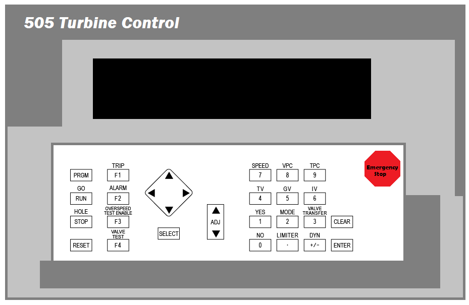
The scroll left (<): moves the display to LEFT.
The scroll left (>): moves the display to RIGHT.
The scroll up ( ^ ): moves the display to TOP.
The scroll left (v): moves the display to BOTTOM.
SELECT KEY: The Select key is used to select the control of the 505 display’s top or bottom line variable.
The @ symbol is used to indicate the line or variable to be adjusted by the adjusting keys only when there is a changeable variable on both lines (dynamics, valve calibration modes) does the “select key” and @ sign determine which line variable can be adjusted.
When there is only one variable per screen the “select key” and @ sign’s position are irrelevant.
ADJ (Adjust) KEY: This key in the run mode, adjusts the or moves the parameter up (larger) and down (smaller).
PRGM (program) KEY: This key selects the
Program Mode when the control is shutdown mode.
Program Monitor Mode is selected in the Run mode.
In the Program Monitor Mode, the program can only be viewed but not changed.
RUN KEY: Initiates a turbine run or start command when the unit is ready to start.
STOP KEY: This key is used to initiate a controlled turbine shutdown. The “Stop” command can be disabled through a Service Mode setting.
RESET KEY: This key is used to reset or clear Run Mode alarms and shutdowns. This key on pressing also returns the control to the (CONTROLLING PARAMETER/PUSH RUN OR PRGM) status after a shutdown.
KEY 0 (NO): Enters 0/NO or disable.
KEY 1 (YES): Enters 1/YES or enable.
KEY 2 (ACTR): Enters 2 or displays the actuator position (Run Mode).
KEY 3 (CONTROL): This key displays the parameter which is in control (Run Mode). Press the scroll down key to display the cause of the last trip, over speed trip status of L/R mode
KEY 4 (CASCADE): This key displays the cascade control information (Run Mode).
KEY 5 (REMOTE): This key displays the remote speed setpoint control information (Run Mode).
KEY 6 (VALVE LIMITER): This key displays the valve limiter information (Run Mode).
KEY 7 (SPEED): This key displays the speed control information (Run Mode).
KEY 8(AUXILIARY): This key displays the auxiliary control information (Run Mode).
KEY 9 (LOAD in kW): This key displays the kW/load or first stage pressure information (Run Mode).
CLEAR: Pressing this key enables to clear Program Mode and Run Mode data entries and takes control out of its present mode.
ENTER: Enters new values in the Program Mode, and allows the “direct entry” of specific setpoint values in the Run Mode.
DYNAMICS (+/–): Accesses the dynamic settings of the parameter controlling the actuator position in the Run Mode. The dynamics adjustments can be disabled through a Service Mode setting (under ‘Key Options’). This key will also change the sign of a value being entered.
(DECIMAL KEY): Enters decimal point in the number being entered from the front panel.
ALARM (F1): This key displays the reason for any alarm condition (last/newest alarm) when the key’s LED indicator is illuminated. Press the Scroll down arrow (diamond key) to display additional alarms.
OVERSPEED TEST ENABLE (F2): The Overspeed Test Enable key allows the speed reference to be raised beyond the maximum controlling speed setpoint to test either the electrical or mechanical over speed trip.
F3 and F4 (function key): Programmable function F3 and F4 keys enable or disable the programmable control functions.
EMERGENCY SHUTDOWN BUTTON: The Octagonal shaped large red button on the front of the enclosure. is an Emergency Shutdown command for the control in case of any emergency.
What are Watchdog Timer and CPU Fault Control?
A watchdog timer and CPU fault control circuit monitors the operation of the processor and controller memory. The microprocessor tries to reset the timer within 15 milliseconds but if it is failed to reset it then CPU fault control activates in order to reset the output.
This resets the CPU, de-energizes all relay outputs, and turns off all milliamp outputs.
How to Raise the Load on a Steam Turbine with Constant Speed?
Steam turbines run at a constant speed with the help of governor control.
The steam supply to the turbine is regulated by the governing system to produce rotation of the steam turbine.
The load on the turbine gets increased by the additional load on the generator which is coupled to the turbine.