In this post, we will learn how to configure analog inputs and outputs in Delta PLC.
In this post, we will see how to configure analog inputs and outputs in a Delta PLC. Let us have a look at each step one by one. I have taken the DVP12SE CPU for reference.
Delta PLC and HMI Course – Join Now
Configure Analog Inputs in Delta PLC
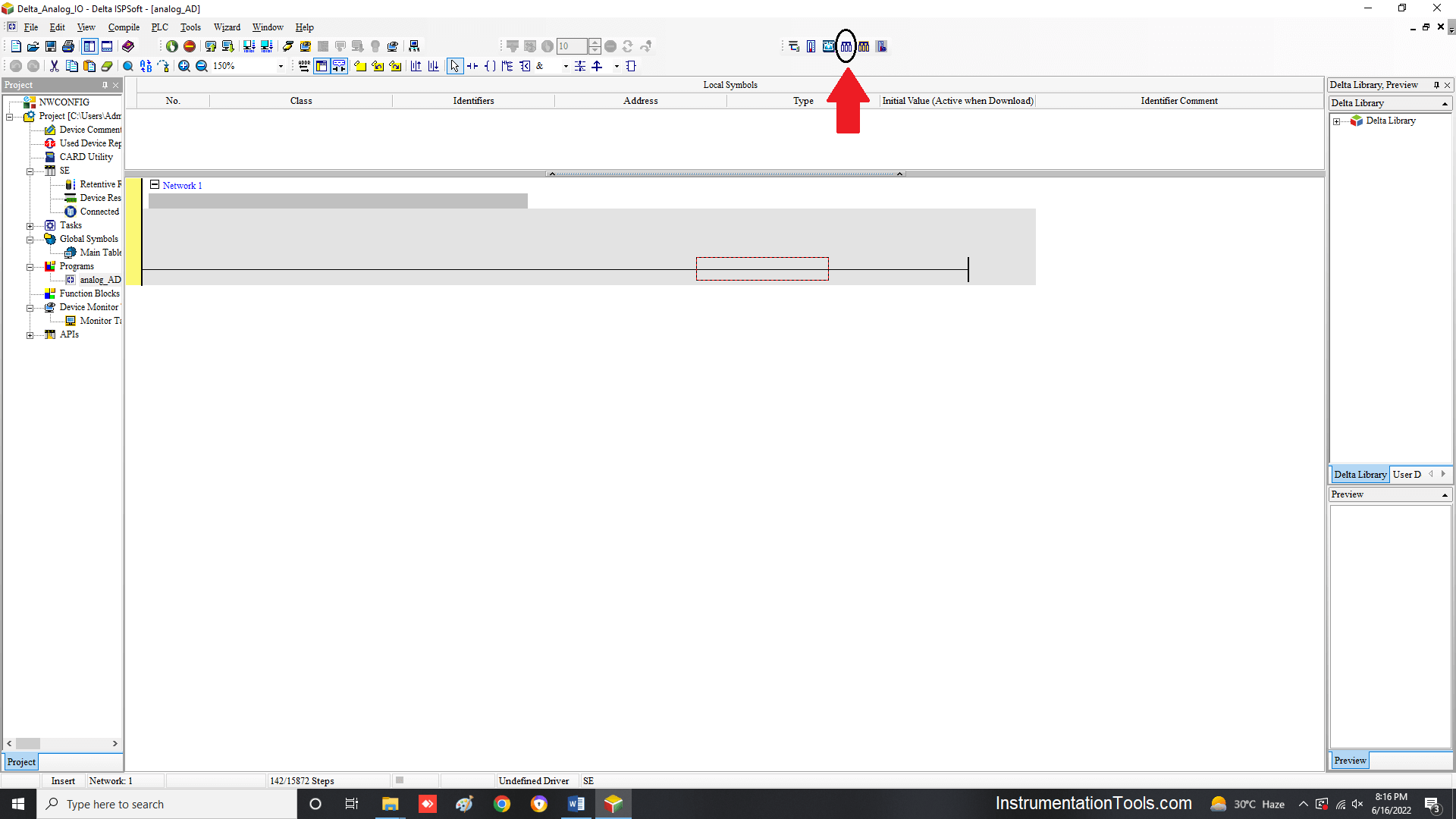
Configure the module that you have by selecting the Auxiliary design of extension modules option as shown in the figure.
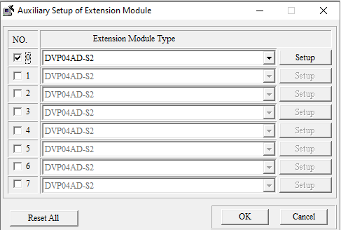
After clicking it, the following dialog window will open where you will be asked to select the model number of the module.
I have selected a 4 channel analog input module in this case.
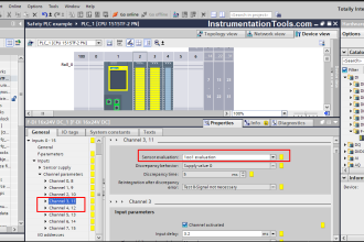
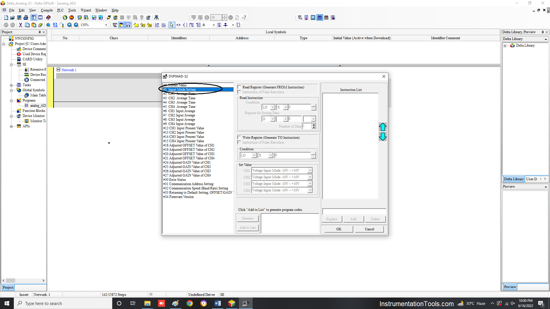
After clicking the setup button in the popup, the following window will appear. Here, you have to choose the Input Mode Setting as shown.
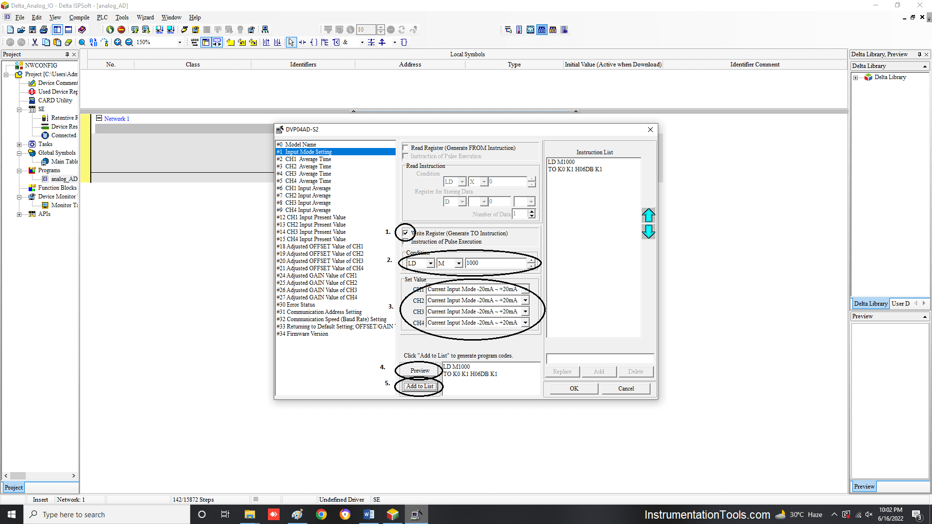
Then, follow the sequence as shown in the figure. First, tick the write register option. Then, select M type data type and put this register value as 1000.
M1000 is a system bit used to denote that the PLC is in a run state. Then, select the type of input you want. In this step, I have selected -20 to 20 mA as the type.
Then, click the preview button. Then, click add to list button. Finally, after everything has been completed.
Click the Ok button to finish the setup. This step will finish configuring your module.
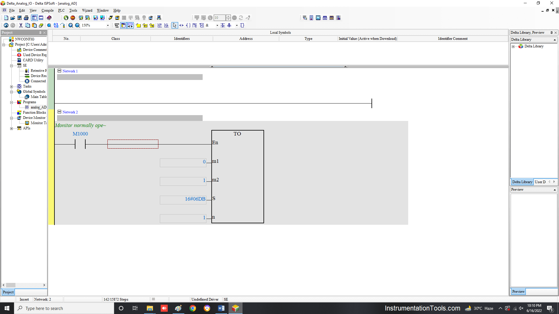
After this, the following block will appear in the ladder rung selected. The hexadecimal code in the S input denotes the code and configuration of the module you have done. It is system generated.
Now, suppose there are 3 modules of the same type in your system. Then too, this block can be used only once. There is no need to add two more rungs of the same type by again setting up the module as discussed before.
Setup is done only when your next module type changes.
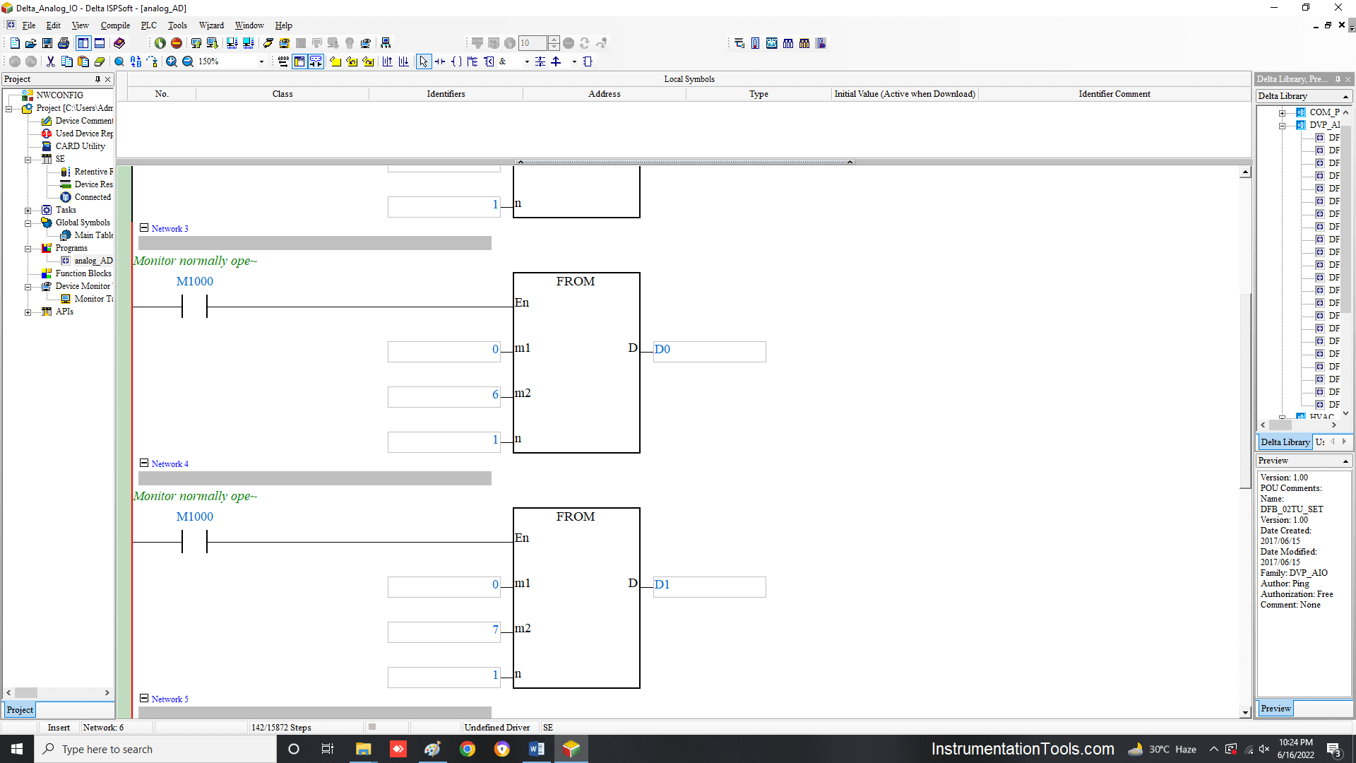
Now, add four rungs after this rung. Four rungs denote four inputs. For example, I have shown two rungs as shown in the below figure. M1 input denotes the slot number of the module you have connected. In this example, 0 means the module is connected in the first slot.
So, if you are connecting the module at the second slot, the number will come as 1. M2 input denotes the channel number in the module. 6 means first input; so in the next rung, I have taken 7 as the input (denoting the second channel).
Other parameters will remain the same. Then, D0 represents the register in the PLC where these analog input counts will be stored.
So, in the next rung, I have used the next available register as D1. Then, adding the remaining two rungs will complete your final setup of the analog input module.
The analog output module configuration will be the same as discussed. The only difference is that instead of four FROM blocks, four TO blocks will come for a 4-channel analog output module. Refer to the following figure.
Here, everything is the same except for the addition of S input. Here, the register which will write the counts to analog output is used (D100). Then, in the next rung, D101 is used.
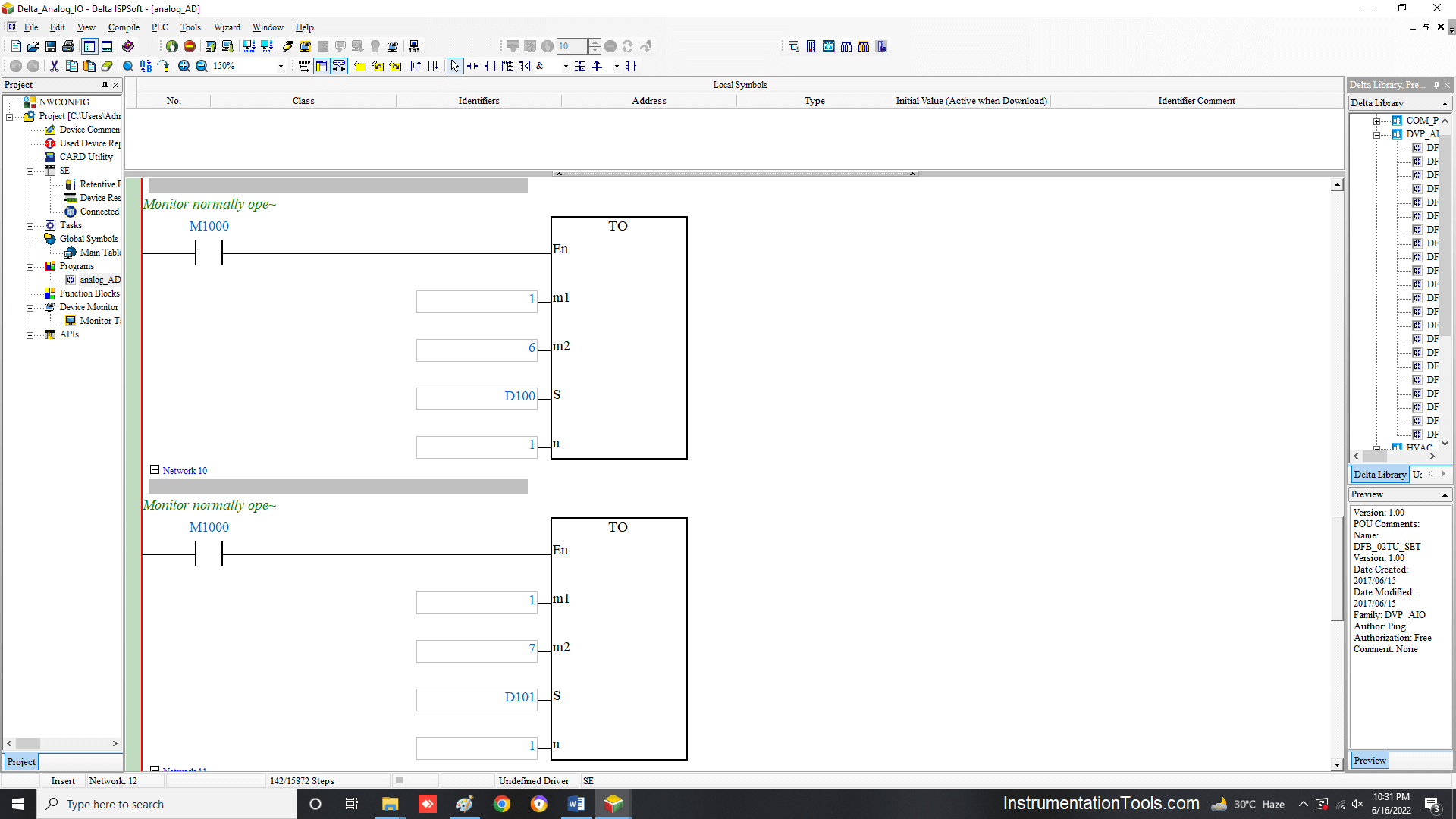
Alternatively, if do not want to write four rungs, then just input the number 4 in the n input. Write only one rung.
Then, the PLC will automatically assign the next three consecutive addresses for the action. But, remember that the next three registers available must be free and not used anywhere else in the program.
In this way, we understand how to configure analog modules in Delta PLC.
If you liked this article, then please subscribe to our YouTube Channel for Instrumentation, Electrical, PLC, and SCADA video tutorials.
You can also follow us on Facebook and Twitter to receive daily updates.
Read Next:
- Redundancy in Siemens PLC
- Allen Bradley PLC Hardware
- Motor Classic Control Circuits
- Control System Cyber Security
- Features of Scada in IoT System