Inst ToolsInst ToolsInst Tools
  • Courses
  • Automation
    • PLC
    • Control System
    • Safety System
    • Communication
    • Fire & Gas System
  • Instrumentation
    • Design
    • Pressure
    • Temperature
    • Flow
    • Level
    • Vibration
    • Analyzer
    • Control Valve
    • Switch
    • Calibration
    • Erection & Commissioning
  • Interview
    • Instrumentation
    • Electrical
    • Electronics
    • Practical
  • Q&A
    • Instrumentation
    • Control System
    • Electrical
    • Electronics
    • Analog Electronics
    • Digital Electronics
    • Power Electronics
    • Microprocessor
  • Request
Search
  • Books
  • Software
  • Projects
  • Process
  • Tools
  • Basics
  • Formula
  • Power Plant
  • Root Cause Analysis
  • Electrical Basics
  • Animation
  • Standards
  • 4-20 mA Course
  • Siemens PLC Course
Reading: Calibration of Temperature Sensor with Indicator
Share
Font ResizerAa
Inst ToolsInst Tools
Font ResizerAa
  • Courses
  • Design
  • PLC
  • Interview
  • Control System
Search
  • Courses
  • Automation
    • PLC
    • Control System
    • Safety System
    • Communication
    • Fire & Gas System
  • Instrumentation
    • Design
    • Pressure
    • Temperature
    • Flow
    • Level
    • Vibration
    • Analyzer
    • Control Valve
    • Switch
    • Calibration
    • Erection & Commissioning
  • Interview
    • Instrumentation
    • Electrical
    • Electronics
    • Practical
  • Q&A
    • Instrumentation
    • Control System
    • Electrical
    • Electronics
    • Analog Electronics
    • Digital Electronics
    • Power Electronics
    • Microprocessor
  • Request
Follow US
All rights reserved. Reproduction in whole or in part without written permission is prohibited.
Inst Tools > Blog > Calibration > Calibration of Temperature Sensor with Indicator

Calibration of Temperature Sensor with Indicator

Learn the calibration of the temperature sensor with an Indicator with a temperature bath, master sensor, and multi-function calibrator.

Last updated: September 28, 2022 3:24 pm
Saurabh Vaidya
Calibration Temperature Measurement
No Comments
Share
5 Min Read
SHARE

Learn the calibration of the temperature sensor with an Indicator with a temperature bath, master sensor, and multi-function calibrator.

Temperature Sensor is broadly classified as RTD Sensor and Thermocouple Sensor.

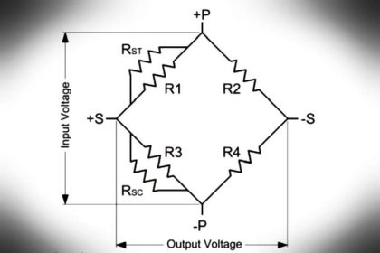
RTD Sensor is further classified as 2wire, 3wire and 4 wire RTD Sensor

Thermocouple Sensor is further classified as Type – B, E, J, K, N, R, S, and T.

Temperature Sensor is connected to Temperature Indicator to display Temperature directly in Units of Temperature i.e. Degree Celsius, Kelvin, Fahrenheit.

This calibration procedure can be used for either RTD or thermocouple calibration and validation.

Calibration of Temperature Sensor

Calibration of Temperature Sensor with Indicator

The below 10 steps will help you to calibrate your temperature sensor using a temperature bath and a master sensor.

Step 1:

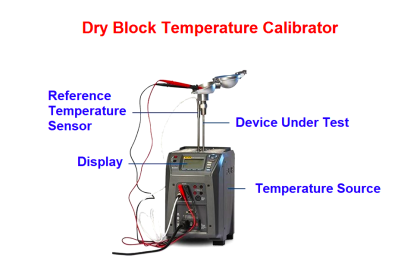
Select the suitable Temperature Bath (Source) for Calibration of Temperature Sensor with Indicator. The temperature sensor to be calibrated is called Unit Under Calibration (UUC).

Let’s choose a temperature bath for our calibration.

Even if Temperature Bath has its own Temperature Indicator/display, it cannot be used as a master for Calibration. It is used as the only source, i.e. only to generate and read the temperature in the bath.

Another calibrated RTD Sensor or Thermocouple is used for Calibration and this is called a Master sensor.

Temperature Bath is selected according to the range of Temperature Sensor.

Step 2:

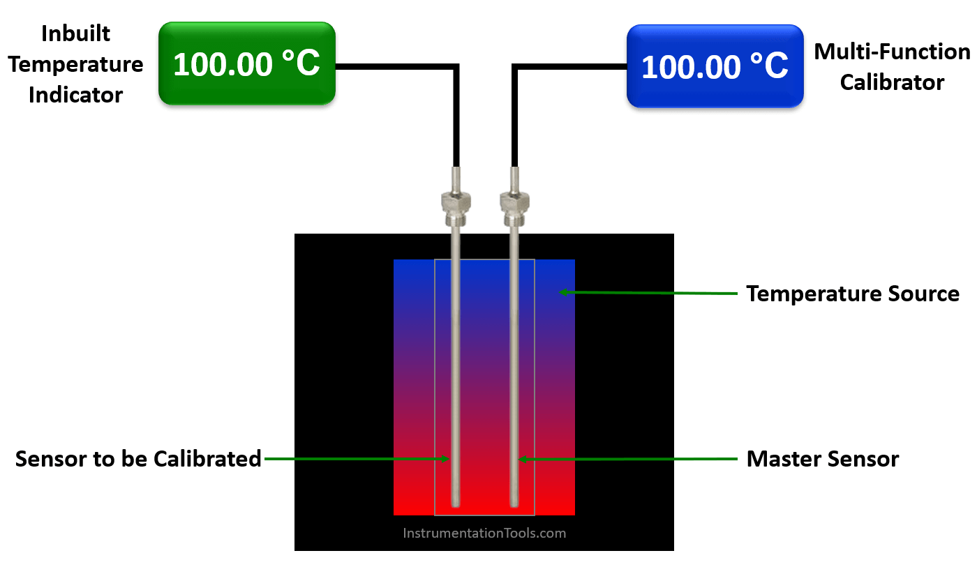
Insert the Temperature Sensor which is to be calibrated into the temperature bath.

In this article, we considered the temperature sensor to be calibrated to have an inbuilt temperature indicator or display. We use this indicator to note down the temperature readings during the calibration. If the temperature sensor does not have an inbuilt indicator then we have to connect a multi-function calibrator to read the temperature readings.

Insert the master RTD Sensor/Thermocouple into another slot of the same Temperature Bath.

Connect a calibrated multi-function calibrator to this master sensor to read the sensor output in temperature units like deg C. (as we don’t have an inbuilt indicator in our master sensor we need to connect a device to read the temperature readings)

Make sure to insert the above two sensors at equal depth to have the ideal effects of the generated temperature.

If you don’t have a multi-function calibrator then you can use calibrated multimeters. Note down the output and do the conversion to temperature using RTD or thermocouple standard temperature tables.

Step 3:

Decide the calibration points of the Temperature Sensor before starting the actual calibration.

For example, I want to do calibration at these points 50 deg c, 75 deg C, 100 deg C, 125 deg C, and 150 deg C.

Step 4:

Set the required setpoint in the temperature bath.

Allow the temperature bath to reach its temperature to the desired setpoint.

Let the bath stabilized at the required temperature.

Step 5:

Note down Master Sensor reading & Temperature Sensor (unit under calibration) with Indicator reading.

As per our example set 50 deg c in the temperature bath, wait 30 seconds, note down master sensor and UUC readings.

Step 6:

Take 5 Readings of each setpoint at the interval of 30 Seconds.

For example, set 50 deg c in the temperature bath, wait 30 seconds, note down master sensor and UUC readings.

Step 7:

If both readings are changing (Master and UUC). Take the average of 5 readings for a single setpoint.

Step 8:

Repeat the above step 4 to step 7 for every setpoint or calibration point.

That means, do the same calibration steps for 75 deg C, 100 deg C, 125 deg C, and 150 deg C setpoints.

Step 9:

After Calibration is completed, set the temperature bath temperature to room temperature.

Step 10:

Switch off the temperature bath after reaching room temperature.

 If the Temperature bath is switched off directly at a setpoint other than room temperature, it loses accuracy, stability, and uniformity.

If you liked this article, then please subscribe to our YouTube Channel for Instrumentation, Electrical, PLC, and SCADA video tutorials.

You can also follow us on Facebook and Twitter to receive daily updates.

Read Next:

  • History of Measurement
  • Calibration Procedure of Voltmeter
  • Different Types of Calibration
  • Magnehelic Gauge Calibration
  • Compare Accuracy and Precision
Don't Miss Our Updates
Be the first to get exclusive content straight to your email.
We promise not to spam you. You can unsubscribe at any time.
Invalid email address
You've successfully subscribed !

Continue Reading

Resistance Temperature Detectors Troubleshooting Tips
Smart Transmitter Calibration Tutorial Part 3
Fieldbus Flow Transmitter Configuration
Calibration Procedure of Voltmeter and Ammeter
Disadvantages of Resistance Temperature Detectors
Instrument Turndown Ratio
Share This Article
Facebook Whatsapp Whatsapp LinkedIn Copy Link
Share
Leave a Comment

Leave a Reply Cancel reply

Your email address will not be published. Required fields are marked *

Stay Connected

128.3kFollowersLike
69.1kFollowersFollow
210kSubscribersSubscribe
38kFollowersFollow

Categories

Explore More

Displacer (buoyancy) Level Transmitter Principle, Limitations, Design, Installation & Calibration
Spiral Bimetallic Thermometer Principle
Thermocouple Temperature Range Questions and Answers
Difference between PT100, PT1000, Nickel RTD and Balco RTD
Pressure Transmitter Calibration at the bench
Functions of Temperature Detectors
What are the Thermocouple Applications?
Displacer Level Transmitter Dry Calibration with Weights

Keep Learning

Pressure Gauge Calibration according to Standard DKD-R-6-1

Pressure Gauge Calibration according to Standard DKD-R-6-1

Pressure and Temperature Gauges

Pressure and Temperature Gauges

Infrared Hydrocarbon Gas Detector Calibration Procedure

Infrared Hydrocarbon Gas Detector Calibration Procedure

Differential Pressure Transmitter Manifold

Field Instrument Calibration Errors

Impulse Line Pressure Testing Procedure

Impulse Line Pressure Testing Procedure

Selection of Weighing Balance

Selection of Weighing Balance and Weight for Calibration

pressure-switch-calibration-procedure

Pressure Switch Calibration Procedure

pH Analyzer Calibration and Troubleshooting

pH Analyzer Calibration and Troubleshooting

Learn More

System architecture

Types of System Architecture used in Industrial Automation

Transformers Questions & Answers Part-2

Transformers Questions & Answers Part-2

Nonlinear Control Systems

Construction of Phase -Trajectories

PLC Problems Troubleshooting

PLC Problems Troubleshooting

HMI Simulation for PID Controller

PID Controller Output Types – PID_PWM and PID_Output

Purpose of Flow Ratio Controller

Identify the Purpose of Flow Ratio Controller

Transmitter Performance and Calibration Frequency

How to Calculate Transmitter Performance and Calibration Frequency?

Structured Text PLC Program for Sequential Process Data Storage

Structured Text PLC Code for Sequential Process Data Storage

Menu

  • About
  • Privacy Policy
  • Copyright

Quick Links

  • Learn PLC
  • Helping Hand
  • Part Time Job

YouTube Subscribe

Follow US
All rights reserved. Reproduction in whole or in part without written permission is prohibited.
Welcome Back!

Sign in to your account

Username or Email Address
Password

Lost your password?