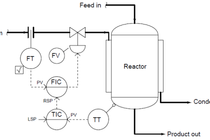
Basic Guide lines to be followed during DCS Loop Checks
(Follow P&ID and Instrument Index):

1. Location of the instrument Tag no. to be checked (As per P&ID)
2. Tag number & Description of the Tag to be checked.
(For Ex: Flash drum level or Instrument air header pressure or Hot oil heater inlet Temp or HP Fuel gas inlet flow)
3. Range & Alarm values for that Particular instrument to be noted. (As per Instrument index or IO List)
4. Unit of that particular tag both in DCS & Field also to be verified.
(Level: m, %, Flow: m3/hr or Nm3/hr or Sm3/hr or Kg/hr, Pressure: barg or bara or mbarg or mmwc or mmhg, Corrosion: mm/yr, Temperature: “C, Control valves: arrow for Fail Open or Fail Close types)
5. For All Transmitters, the checks to be done for 0%, 50% & 100% of the total range.
6. If the Flow Transmitters is of DP type, checks to be as follows: For Eg. For Transmitter Range: 0 to 100 m3/hr & DP Range: 0 to 500 mbar, 0% (0 mbar) = 0 m3/hr; 25% (125 mbar) = 50 m3/hr; 50% (250 mbar) = 70.7 m3/hr; 75% (375 mbar) = 86.6 m3/hr; 100% (500 mbar) = 100 m3/hr
7. All Level Transmitters to be checked only with water. If they are not using water (except vessel mounted Radar Transmitter), report in DPR that LIT was checked with mA & to be checked with water again.
8. For DCS Transmitters, normal checks, Alarm values & its recovery values to be checked by simulating from field.
9. If Instrument Index & Data Sheet Ranges are not matching, please record in your DPR (Daily Progress Report).
10. For all Alarm values simulation, check for alarm in Current Alarm Manager (CAM). When an Alarm comes, it has to blink in graphics in Red, if we accept it will become static.
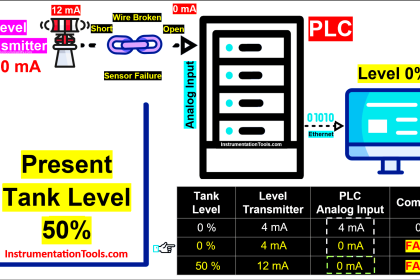
11. For ESD Transmitters, Alarm values, LL or HH or either & SC (Short Circuit), OC (Open Circuit) to be checked by simulating from field.
12. Alarm description to be checked (For Ex: IA header pressure low or Hot oil heater all temp. High or HP fuel gas inlet flow low)
13. Color of the Display in Graphics also required to verify.
14. For Control valves, the stroke checks to be done for 0%,25%.50%, 75%, 100%, 75%, 50%, 25% & 0%.
The valve openings actually in Field to be confirmed from Person on Field & Recorded in Loop checks report.
For Checking Fail Open type, Close the valve, isolate the instrument air supply & reduce the air pressure by bleeding off (the Control Valve should open & opening in DCS & Field should match).
For Checking Fail Close type, open the valve 50%, isolate the instrument air supply & reduce the air pressure by bleeding off, (the Control Valve should close). Color change also to be checked.
15. Manual & Auto change over from Face plate Controllers to be checked & control valve moving action, in case of Control valves.
(Direct & Reverse action of Controllers as per control narrative also to be verified). Some of the controllers, we have seen Action given in Control narrative is wrong. Please identify & report in DPR.
16. Check Control Valves, XV’s, SDV’s, BDV’s either permanent instrument air tubing is connected or not. If not, don’t check that valves. BDV’s, few SDV’s, few XV’s, few PCV’s has Volume Bottle. Ensure Volume bottle is connected or not as per design. Otherwise report in your DPR.
17. During SDV Loop Checks: Open, Close, Fail Open, Fail Close, reset, PST & mismatch alarm to be checked. Color change in Graphics & Face plate for SDV’s to be checked while open & close operation.
Also Read : Basics of Loop Checks
Ensure the following
a. Valve Open & Close (Color change in Face plate & Graphics & Field position). For Open, we should get ZSO alarm & for Close, we should get ZSC alarm. (ZSO & ZSC also refers as ZSH/ZSL or may change from company to company)
b. SOV energise & de-energise (Color change in Face plate & Graphics). For SOV command, we should get SDY or SDC alarm (normally given for Close Command).
c. For Reset alarm, we should get HS-XXX alarm.
d. For PST (Partial Stroke Test), we should get ZY-XXXX alarm.
c. Time taken for Open & Close in Field, after the signal given, to be checked. (Check as per Data sheet, it is operating or not) & note in your DPR if it takes more than 20 sec for close.
d. Fail Position of SDV’s: Fail close, Fail Open or Fail Last as per P&ID & data sheet in Field. e. If your get mismatch alarm, report in your DPR.
e. Some of the SDV’s are Fail last (meaning it will remain in last position). It is also to be checked by cutting of air & SOV power supply.
f. Some SDV’s has DCS Hand Switch (particularly MEG area, from DCS Hand Switch operation from DCS to be checked). Open & close timings to be also checked. If it is more than given in datasheet, please record in your DPR.
g. Some of the SDV’s (MEG) has Volume Bottle. It is also to be checked. If not, report in your DPR. Please write in your DPR – what are all we checked during SDV/XV/BDV/MOV loop checks: like Open, Close, SOV close command, Field Reset, PST alarm checked. (If it has checked & we got alarm).
18. During BDV Loop Checks: Open, Close, Fail last condition, Operation from Volume Bottle also to be checked. Color change in Graphics & Face plate for SDV’s to be checked while open / close operation.
Ensure the following
a. Valve Open & Close (Color change in Face plate & Graphics & Field position). For Open, we should get ZSO alarm & for Close, we should get ZSC alarm.
b. SOV energise & de-energise (Color change in Face plate & Graphics). For SOV command, we should get BDY1 for Open Command.
c. Fail Last Position. (After opening the valve, isolate air & isolate power supply to SOV, the valve should be in open condition (i.e.) last position)
19. During MOV Loop Checks:
a) Get Clearance from Respective Team Lead.
b) Ensure the valve is smoothly operated (Full Open & Close) with Hand Wheel. (To engage the Hand wheel, depress the Hand lever & turn the Hand wheel to engage the clutch. Operate one turn & then release the lever).
c) After ensuring it is operated freely, Give Clearance for loop checks.
d) Put the corresponding switch in “IN CIRCUIT” position in Field.
e) Then turn the selector switch provided in MOV in “Local” mode & then fully operate using the Open/Close switch provided in MOV. Check for smooth operation. If any Jerky/abnormal operation found, stop checking.
f) Check for color change in MOV face plate & graphics during Open/Close operation.
g) Check for alarms for Open/Close (ZI-XXXX alarm)
h) Finally keep MOV in open condition (say, 20 or 30%) & then using Hand wheel operate the MOV. It should Open / Close irrespective of the Power Supply.
i) Some MOV’s can be opened from DCS (see P&ID for Hand switch). Turn the selector switch in MOV to “Remote Mode”, then operate from DCS – Full Open/Close.
j) If any abnormalities found in Graphics, Faceplate or Field like Mismatch, Battery Low, Device Alarm, Jerky Operation, not operating when power supply is ON etc. report in your DPR.
k) Don’t forget to check the Hand wheel Operation when power supply is “ON”.
20. Please guide Field Engineer and get feed back from them while loop checking for deviations.
21. It is the DCS Engineer responsibility to get the Field Engineer to do all checks & get Punch Points from Field. During Valve Checks, Field Person is necessary.
22. If there is any deviation from the above, please write your observations in Loop Test Report & DPR.
NOTE: Mark in P&ID daily after loop check is completed. It will be useful for tracing the balance loops.
Also Read : Field Instruments Loop Checks Procedure
Guide lines to be followed in Field during DCS Field Loop Checks (with P&ID):
1. Location of the instruments (As per P&ID).
2. Position of that instrument in field & Canopy for that instrument. (Viewing the display, isolation valve accessibility – should not be difficult, direction of control valve, Color & instrument tubing for Fail close – Green color / Fail open – Red color, Flow transmitters – HP & LP impulse tube tapings)
3. Flow Orifice Tapping : For Liquid Service – it should be from bottom (45 Deg C both sides) & transmitter should be fixed below the tap-off point; For Gas Service – it should be from bottom (45 Deg C both sides) & transmitter should be fixed above the tap-off point.
4. Pressure Transmitter Tapping: For Gas Service- It should be above the tap-off point; For Liquid Service – It should be above the tap-off point.
5. Name plate of that instrument (Should match with P&ID and DCS).
6. Display of the readings with parameters on that Transmitter. (Should be clear & check for any damage).
7. Unit of that particular tag – Should match with DCS. (Level: %, Flow: m3/hr or Nm3/hr or Sm3/hr or Kg/hr, Pressure: barg or bara or mmwc, Corrosion: mm/yr, Temperature: °C).
8. For Transmitters, the checks will be done for 0%, 50% & 100% of the total range. The readings displayed to be counter checked with the person on DCS.
9. For Control valves, the stroke checks will be done for 0%, 25%. 50%, 75%, 100%, 75%, 50%, 25% & 0%. The valve openings actually in Field to be informed to the Person on DCS.
10. If there is any deviation from the above, please note & inform your observations to the Person in Control Room, so that he will write in Loop Test Report & DPR.
Also Share any other Points if we missed in the above mentioned list via comments section
Also Read: Guidelines for Logic Checks


Dear Sir,
Thank you very much for updating valuable knowledge but please provide one PDF file save option to download the soft copy. Here there is no option of downloading or copying the paragraph please help, only print & email option is available.
print option showing the only hard copy of print no soft copy option available in print.
Respected Sir,
I’m Veerabhadra Gouda BE instrumentation Engineer working in JSW Steel in Bellary & I’m Big Fan Of U , U R My Guru, I’m Waiting 4 Such A Person Like U Thanks Bharadwaj Garu..
this theoretical basic ok but also put same job video
Such a wonderful article for loop check starters.
Good job author…Keep up the Excellent Job….
Thank you for sharing your valuable knowledge
very useful info …. thank you so much for sharing the knowledge … its all summary and refresher to my college years and years of experience in industry … also serve as guidelines
Amazing information. Practical dos and donts… Things to be checked carefully during pre-commissioning….
A very forum
Thanks for sharing
greater giving greater living
Wow, a lot of mistakes are in here. How can you state that 500mbar equals any flow without checking the actual flow element.
Level checks should be done with the correct liquid. Diesel for example.
For valves it is crucial to know what the actual response is instead of 25% steps. Does it overshoot? Hunt? Takes for ever to get there?
Hi Stephen could you please share some related article to know more about your comments.
Thanks
There are times when the alarm and shutdown level is simulated by injected signal eg 4 to 20 mA current, where it is not possible to use actual fluid.
These information are extremely rich and I really want to thank the author for this details information.
please I want to beg if it is possible we get this information in pdf .
dear sir
it is a great job ,thanks a lot for your efforts
4. Pressure transmitter tapping: For Liquid Service- It should be above the tap-off point.
I think You should change above to below
Bro kindly tell me that,what is DPR in ur Article..
Highly appreciated for sharing all this knowledge.