Inst ToolsInst ToolsInst Tools
  • Courses
  • Automation
    • PLC
    • Control System
    • Safety System
    • Communication
    • Fire & Gas System
  • Instrumentation
    • Design
    • Pressure
    • Temperature
    • Flow
    • Level
    • Vibration
    • Analyzer
    • Control Valve
    • Switch
    • Calibration
    • Erection & Commissioning
  • Interview
    • Instrumentation
    • Electrical
    • Electronics
    • Practical
  • Q&A
    • Instrumentation
    • Control System
    • Electrical
    • Electronics
    • Analog Electronics
    • Digital Electronics
    • Power Electronics
    • Microprocessor
  • Request
Search
  • Books
  • Software
  • Projects
  • Process
  • Tools
  • Basics
  • Formula
  • Power Plant
  • Root Cause Analysis
  • Electrical Basics
  • Animation
  • Standards
  • 4-20 mA Course
  • Siemens PLC Course
Reading: Ball Float Steam Trap
Share
Font ResizerAa
Inst ToolsInst Tools
Font ResizerAa
  • Courses
  • Design
  • PLC
  • Interview
  • Control System
Search
  • Courses
  • Automation
    • PLC
    • Control System
    • Safety System
    • Communication
    • Fire & Gas System
  • Instrumentation
    • Design
    • Pressure
    • Temperature
    • Flow
    • Level
    • Vibration
    • Analyzer
    • Control Valve
    • Switch
    • Calibration
    • Erection & Commissioning
  • Interview
    • Instrumentation
    • Electrical
    • Electronics
    • Practical
  • Q&A
    • Instrumentation
    • Control System
    • Electrical
    • Electronics
    • Analog Electronics
    • Digital Electronics
    • Power Electronics
    • Microprocessor
  • Request
Follow US
All rights reserved. Reproduction in whole or in part without written permission is prohibited.
Inst Tools > Blog > Process > Ball Float Steam Trap

Ball Float Steam Trap

Last updated: May 18, 2018 7:43 pm
Editorial Staff
Process
No Comments
Share
1 Min Read
SHARE

In general, a steam trap consists of a valve and a device or arrangement that causes the valve to open and close as necessary to drain the condensate from piping without allowing the escape of steam. Steam traps are installed at low points in the system or machinery to be drained.

Ball Float Steam Trap

Ball Float Steam Trap

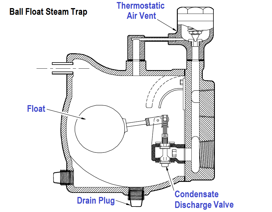
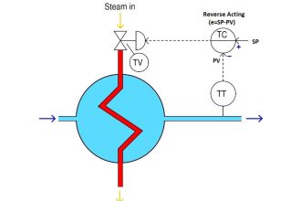
Figure : Ball Float Steam Trap

A ball float steam trap is illustrated in Figure. The valve of this trap is connected to the float in such a way that the valve opens when the float rises. When the trap is in operation, the steam and any water that may be mixed with it flows into the float chamber. The water, being heavier than the steam, falls to the bottom of the trap, causing the water level to rise.

As the water level rises, it lifts the float; thus lifting the valve plug and opening the valve. The condensate drains out and the float moves down to a lower position, closing the valve before the condensate level gets low enough to allow steam to escape. The condensate that passes out of the trap is returned to the feed system.

Don't Miss Our Updates
Be the first to get exclusive content straight to your email.
We promise not to spam you. You can unsubscribe at any time.
Invalid email address
You've successfully subscribed !

Continue Reading

Why Restriction Orifice is some distance from Blowdown valve ?
Why Counter-current Heat Exchangers are better than Co-current?
What is a Deaerator? – Working Principle
Inhouse Moisture separator for Pneumatic Systems
Process Design of Instrument Air System
Refrigeration Compressor Turbine Not-tripping when needed Trip
Share This Article
Facebook Whatsapp Whatsapp LinkedIn Copy Link
Share
Leave a Comment

Leave a Reply Cancel reply

Your email address will not be published. Required fields are marked *

Stay Connected

128.3kFollowersLike
69.1kFollowersFollow
210kSubscribersSubscribe
38kFollowersFollow

Categories

Explore More

Superheated Steam Temperature Control System
Strainers
CO2 Absorber Corroded Wall Thickness & Weld Building
Introduction to Chemical Dosing System
Blowout preventer (BOP) Principle
Pumps Quiz
Reciprocating Compressors
What is a Compressor? Types of Compressors

Keep Learning

Fuel Boiler

Boilers

Water Treatment Industry

Water Softening Systems in Water Treatment Industry

Compressor IP Case Discharge Temperature Gradually Increases

Compressor Anti-Surge Control near-miss incident

Design Engineering of Process Plant Project

Process Engineering Roles & Responsibilities – Design Company

Water Treatment Plant

Difference Between ETP, STP, and WTP – Treatment Plants for Water

Filters in Compressors

Filters in Compressors

Working of Air Compressor

Working of Air Compressor – Types – Control Techniques

Pressure Reducing and Desuperheating Station (PRDS)

Pressure Reducing and DeSuperheating Station (PRDS)

Learn More

Induced Draft Cooling Tower

Cooling Tower fan FRP fan blades saves and saves

Smart Transmitter Calibration Tutorial

Smart Transmitter Calibration Tutorial Part 1

Strain Gauge Accelerometer

Strain Gauge Accelerometer

PLC Program for Tank Heating Control using Heater

PLC Programming for Tank Heating Control using Heater

Solid State Relay Working Principle

What is a Solid State Relay? – Working Principle, Types of Control

Facts of Control Valves

Facts About Control Valves

PID Controller Graph - 3

PID Controllers Graphical Analysis

Stilling well in liquid level measurement

Stilling Well in Interface Level Measurement System

Menu

  • About
  • Privacy Policy
  • Copyright

Quick Links

  • Learn PLC
  • Helping Hand
  • Part Time Job

YouTube Subscribe

Follow US
All rights reserved. Reproduction in whole or in part without written permission is prohibited.
Welcome Back!

Sign in to your account

Username or Email Address
Password

Lost your password?