The basic layout of every 4-20mA loop consists of a power supply, a transmitter, and passive loop devices. The supply produces the energy to run the loop. The transmitter controls the current through the loop.
The loop devices provide feedback to the world, whether it is an indicator displaying the measured quantity from the transmitter, or some type of relay output control device.
Loop devices can also be passive (loop powered) or active (has a power supply) signal transformation devices. For instance, these can be isolators of transform the 4/20mA to some other electrical signal, such as 0/10V.
Troubleshooting Current loop

To troubleshoot a 4/20mA loop electrically, one must use a Digital Volt Meter. The DVM should be able to read Volts and milliAmps DC.
Besides the usual sources, a suitable DVM can be found in the hardware stores, auto parts stores, and department stores.
4-20mA Current loop
One should also know how to use the DVM. It is possible to damage the loop, the DVM, or yourself by using it improperly. Voltage is measured by attaching the DVM leads across the device, essentially attaching the DVM in parallel with the device.
Current is measured by attaching the DVM in series with the circuit. The loop wire must be disconnected, and the DVM attached into the circuit to cause all the current to run through the DVM.
A malfunctioning 4/20mA loop can be caused by many things. The first thing to do is determine where the problem is. Problems can be caused by power, wiring, or loop device issues.
If the loop does not appear to function in any manner then one should first check the power and wiring. If it appears that the loop is functioning in some manner then the nature of the malfunction becomes important.
If the only malfunction is that the display is reading the wrong numbers, then you should first investigate setting up the display. Please refer to the display manual or the setting up document in this series. Otherwise, start with the loop device section.
Power
The first step in troubleshooting any circuit is to check the power supplies. Measure the loop power supply voltage, and ensure that it is at the proper level.
1) If the supply output is zero, determine if the supply is being powered, if a fuse is blown, or if the supply is damaged.
2) If the supply voltage is a little low, check to see if the supply is unregulated. Variation of the output voltage with load is normal for an unregulated supply.
3) If the supply is regulated, and the output is low, it may be caused by a high loop load. Disconnect the loop and measure the voltage output. If the voltage output remains at the faulty level, the supply might be bad. If the voltage output level returns to the specification a high loop load might be the cause. Insert a milliamp meter between the supply and the disconnected wire to measure the loop current.
A loop current much larger than 26mA would indicate an excess load on the loop. Possible causes for excessive loop current are miswiring, a ground loop, and a problem with the transmitter. Ensure that the transmitter is installed with the proper polarity.
If the current is less than 22mA and the supply output voltage is low, then the power supply could be faulty.
Wiring
Check the wiring. The power supply + terminal should be run to the + terminal of the first item in the loop. The – terminal of the first item on the loop should be run to the + terminal of the second item on the loop, and so on until the wiring returns to the – terminal of the power supply.
With the loop supply powered, measure the voltages across the devices in the loop. The voltages on the loop devices should agree with the specifications for those devices, and the voltage polarity must agree with the + and – of the terminal block.
If the voltages across all the loop devices is zero, and the loop supply is within specification, then there is a break in the loop. If most, if not all of the voltage occurs across any one of the loop devices, than there is a problem with that device.
Loop Devices
Troubleshooting a loop depends on the devices in the loop. The most important troubleshooting step is to make sure that is it wired properly. Hours of time and phone support have been wasted because the device was wired improperly.
Problems that loop powered indicators exhibit usually are the result of improper scaling, incorrect wiring, or electronic failure. A display that is improperly scaled will react to the 4/20mA signal, moving up and down in a predictable way, but not displaying the proper values for the loop. Correcting this requires identifying the range of the 4/20mA transmitter and scaling the display to these values.
A display that is improperly wired most probably will not turn on. A DVM measurement of the voltage across the terminals and comparing this to the markings will identify if the polarity is correct.
An electronic failure most commonly results in a display that will not turn on, which makes being able to identify that the display is properly wired important. Obvious faults like missing digits, missing segments, constant indication, etc are easier to diagnose.
Problems that AC powered indicators exhibit usually are the result of improper scaling, incorrect wiring, or electronic failure. A display that is improperly scaled will react to the 4/20mA signal, moving up and down in a predictable way, but not displaying the proper values for the loop. Correcting this requires identifying the range of the 4/20mA transmitter and scaling the display to these values.
The fact that the indicator is powered introduces another fault condition. If the display indicates a value below the 4mA scaling point by roughly -25% of the span, one can be sure that the loop current is not passing through the indicator. For instance an indicator scaled 0.0 to 23.1 will indicate approximately -5.7 with no current going through it.
Electrical problems with the indicator that interfere with it’s proper operation, such as a blown power supply, soft power supply, malfunctioning electronics, etc aren’t part of troubleshooting a 4/20mA loop, unless the loop is being powered by a supply that is part of the indicator and one can continue by repairing the indicator to resolve these issues.
Problems with transmitters usually occur because of wiring problems. The loop and the sensor must be wired properly. Transmitters can be damaged by attaching power to the wrong terminals.
If the device is wired properly, measure the voltage across the transmitter to check the polarity and to make sure that it has sufficient voltage to operate by comparing the measured voltage to the minimum in the specifications for that transmitter. Sensors must be properly attached, check the wiring diagram for the transmitter to ensure that it is proper.
Problems with transducers are the same as transmitters, except that the sensor is part of the device so the sensor does not have to be checked.
Problems with isolators usually occur because of wiring problems. There is often confusion as to where power is applied and how to wire the isolator into the circuit. Isolators have many configurations:
some require that the loop is powered on the input and the output, some transfer energy across the isolation barrier and therefore only require one side to be powered, and some AC powered units provide energy for either side of the isolation barrier.
Also Read: Why Current Loop so Popular ?
Sometimes isolators require that the circuitry on both sides of the isolation barrier is properly connected for it to operate, so nonfunctioning on one loop might be caused by a problem on the other side of the barrier.
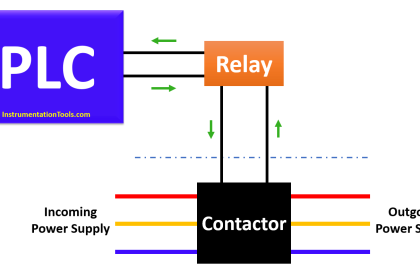
Problems with Programmable Logic Controllers can be of several varieties. Several things need to be checked to properly incorporate a PLC into a loop. PLCs often have terminals that will allow you to attach the 4/20mA loop in several ways. Attaching the 4/20mA loop to one set of terminals will allow the PLC to power the loop, while one must attach to a different set of terminals if the loop is externally powered.
Another issue is that the PLC can, and often does, connect the 4/20mA loop to earth ground because the input is not isolated. This causes a problem with the loop when any other point on the loop is also connected to earth ground because the multiple earth grounds create an alternate pathway for the loop current to flow through. Some sensors, such as pH and thermocouple, are inherently electrically connected to what they are measuring.
Most loop designs ground the loop at the power supply as a noise reduction measure. These considerations strongly suggest that any loop design be thoroughly analyzed to avoid designing in problems that are only realized when trying to get the system up and running.
One way to troubleshoot a loop is to identify what the loop is doing, instead of what it is not doing. For instance, if you can say that the loop current is within the specification, then you can say that the power supply and transmitter are probably fine.
One problem that is perplexing is that the loop operates fine, until if gets to a certain level and then it doesn’t operate properly. This is usually caused by too many devices on the loop. Each of the devices in the loop will have some listed power requirement or loop burden.
For instance, a transducer might require a minimum of 14V, a loop powered display 5V, a signal isolator 7V, and a controller might have a 20 Ohm input. Using Ohm’s law, that 20 Ohm input becomes 0.02A * 20 Ohms = 0.4V.
Now total the requirements for all the devices in the loop, and 14 + 5 + 7 + 0.4 = 26.4V. A loop that requires 26.4V to operate but is powered by a 24V supply will not operate properly.
A digital multimeter is an essential tool in analyzing a loop. Using a tool to ensure voltage levels and measuring the current through the loop is the fastest way to verify operation and isolate problems.
Another useful tool is a loop simulator / calibrator which will allow the user to set the loop current to known levels, as well as being able to individually power up and test the functionality of the loop devices.
4-20mA Current Loop Questions & Answers
What is a 4mA to 20mA signal?
The 4mA to 20mA signal is an industrial standard electrical signal that was designed to send information from one point to another. The 4/20mA signal can represent anything, and be scaled to any range of that quantity. What this means is that the 4/20mA signal can represent temperature, pressure, depth, humidity, or any number of things.
It also means that the 4/20mA signal can represent any range of values for that quantity, such as 0% to 100%, or 20% to 80%. Exactly what a 4/20mA signal represents is defined by the transmitter (sometimes referred to as a transducer) that is controlling the signal.
What components are needed for a 4mA to 20mA signal?
The components that are typically part of a 4/20mA installation are:
1) A power supply to provide the electricity for the loop
2) Wire (usually a “twisted pair”) to carry the electrical current
3) A transmitter to control the current through the circuit
4) A sensor wired to the transmitter to detect the quantity being measured
5) An indicator to show what the transmitter is measuring
6) A controller to act on the measured signal
Note: power supply, indicator, and controller are combined into one device. Sometimes the sensor and transmitter are combined into one device
Sensors, transmitters, transducers: What?
Sensors are used to measure something, like temperature, pressure, weight, humidity, etc. The signal that a sensor makes is very small.
A transmitter consists of circuitry that amplifies this small signal and adjusts it to the 4/20mA output. When a sensor and a transmitter is designed and built as a single unit, it is frequently called a transducer.
How to wire a 4/20mA system?
The sensor is always wired to the transmitter. The other components of the 4/20mA system get wired in series, one after the other. Take a look at the various components, the transmitter, display, controller, and power supply. They all will be marked with a “+” power and a “-“ power terminal.
Connect the devices together so that the “+” power terminal of the power supply goes to the “+” terminal on the first device, the “-“ terminal of the first device to the “+” terminal of the second device, the “-“ terminal of the second device to the “+” terminal of the third device, and so on and so on until one wires back to the “-“ terminal of the power supply.
Because the wiring starts at the power supply and goes from one device to another, the 4/20mA system is commonly called a 4/20 loop.
What are the things need to know before design a 4/20mA loop?
The first task is to make sure that the power supply voltage is large enough to drive all the devices on the loop. The standard loop power supply is voltage for a Look on the data sheets for all the devices for an entry that identifies “power requirements”, “loop burden”, “drop”, or “impedance”.
We are looking for a value of voltage or resistance. Each device is going to require a certain amount of voltage from the loop to operate.
We will add these voltages together to make sure that they are less than the voltage available from the power supply. If the value is given as a resistance, we will use ohms law to convert it to a voltage.
Ohm’s law states that voltage equals current multiplied by resistance, so multiply the resistance by 0.02 and the resulting figure is the voltage we desire. Frequently a transmitter is labeled as “Power: X to Y Volts”. We will use the lower of the voltages in the calculation.
If the devices in the loop require more voltage to operate than the power supply delivers.
The second task is to identify all points in the loop that might be attached to earth ground. Devices like PLCs and power supplies frequently attach the connections to earth ground. Some sensors, like thermocouples, might not be electrically isolated and cause an unintended earth point.
Having more than one earth point in the loop will cause the loop to malfunction because current can flow between the earth points instead of through the wires.
The third task is to pick the cable. There are many existing solutions supplied by cable manufacturers. We recommend a twisted pair cable of at least #22 AWG.
The exact cable a particular installation will require will depend on the environment the cable is run through and the length of the cable. This document contains general advice and is not meant as a formal engineering solution to any particular application.
How do Get the display(s) on the 4/20mA loop to read properly?
A 4/20mA signal can represent anything, but the values that the loop represents are always defined by the transmitter (or transducer) in the loop. The range of the transmitter identifies the values being transmitted at 4mA and at 20mA.
Obtain the range of the transmitter and you will know what to set the display(s) to. Sometimes a transmitter sends a signal related to but not a direct measure of the desired quantity.
For instance, a pressure transducer is often used to measure the depth of a liquid, such as in wastewater facilities. It is common to use a 0/10psi pressure transducer, which would measure 0/23.1 feet of water. In cases like this it is necessary to apply math to achieve the proper results.
Sometimes scaling the display becomes confusing because what the transmitter is sending is very different from what is desired to display.
The best tool one can use to solve this problem is to draw a diagram of the installation, placing the sensor, labeling the desired measurement points, and the range that the sensor will measure. If necessary convert the sensor’s unit of measure into the display unit of measure (PSI to feet, for example) then add or subtract as necessary to get the scaling.
As an example, let’s say a 40PSI pressure transducer is mounted 75 feet down a well. The desire is to indicate the distance between the top of the well and water. 40 PSI * 2.311 feet/PSI = 92.4 feet.
The transducer is 75 feet down, so 4mA = -75 feet. Therefore, at 20mA the display should read -75 + 92.4 = 17.4 feet.
The loop is turned on but it isn’t doing anything, Why ?
A 4/20mA loop consists of many parts, and any one of the parts can be a problem. The first step is to check the wiring. Ensure that contact is made and to the correct terminals. The positive side of the loop devices should be wired toward the positive side of the power supply, the negative toward the negative.
A digital multimeter is an invaluable tool in troubleshooting a 4/20mA loop. Measure the voltage on the power supply to ensure that it powers up to the rated voltage.
Measure the voltage across the transmitter to ensure that the voltage is larger than the minimum requirement and that the polarity of the voltage is correct as labeled on the transmitter. A frequent cause of loop failure is due to the transmitter being wired up backwards.
If you liked this article, then please subscribe to our YouTube Channel for PLC and SCADA video tutorials.
You can also follow us on Facebook and Twitter to receive daily updates.
Read Next:
- 4-20 mA Loop Splitter
- Signals Wiring Techniques
- Internal Powered Modems
- Passive vs Active Transmitter
- Three Phase Wattmeter


Very good.
excellent lessons
Very informative.