Inst ToolsInst ToolsInst Tools
  • Courses
  • Automation
    • PLC
    • Control System
    • Safety System
    • Communication
    • Fire & Gas System
  • Instrumentation
    • Design
    • Pressure
    • Temperature
    • Flow
    • Level
    • Vibration
    • Analyzer
    • Control Valve
    • Switch
    • Calibration
    • Erection & Commissioning
  • Interview
    • Instrumentation
    • Electrical
    • Electronics
    • Practical
  • Q&A
    • Instrumentation
    • Control System
    • Electrical
    • Electronics
    • Analog Electronics
    • Digital Electronics
    • Power Electronics
    • Microprocessor
  • Request
Search
  • Books
  • Software
  • Projects
  • Process
  • Tools
  • Basics
  • Formula
  • Power Plant
  • Root Cause Analysis
  • Electrical Basics
  • Animation
  • Standards
  • 4-20 mA Course
  • Siemens PLC Course
Reading: Multimeter & Megger Principle
Share
Font ResizerAa
Inst ToolsInst Tools
Font ResizerAa
  • Courses
  • Design
  • PLC
  • Interview
  • Control System
Search
  • Courses
  • Automation
    • PLC
    • Control System
    • Safety System
    • Communication
    • Fire & Gas System
  • Instrumentation
    • Design
    • Pressure
    • Temperature
    • Flow
    • Level
    • Vibration
    • Analyzer
    • Control Valve
    • Switch
    • Calibration
    • Erection & Commissioning
  • Interview
    • Instrumentation
    • Electrical
    • Electronics
    • Practical
  • Q&A
    • Instrumentation
    • Control System
    • Electrical
    • Electronics
    • Analog Electronics
    • Digital Electronics
    • Power Electronics
    • Microprocessor
  • Request
Follow US
All rights reserved. Reproduction in whole or in part without written permission is prohibited.
Inst Tools > Blog > Electrical Theory > Multimeter & Megger Principle

Multimeter & Megger Principle

Last updated: August 13, 2018 2:33 pm
Editorial Staff
Electrical Theory
No Comments
Share
3 Min Read
SHARE

The multimeter can be used as an ammeter, an ohm meter, or a voltmeter. Meggers are used to measure insulation resistance.

Multimeter

The multimeter is a portable single instrument capable of measuring various electrical values including voltage, resistance, and current. The volt-ohm-milliammeter (VOM) is the most commonly used multimeter.

The typical VOM has a meter movement with a full scale current of 50 µA, or a sensitivity of 20 KΩ/V, when used as a DC voltmeter. A single meter movement is used to measure current, AC and DC voltage, and resistance. Range switches are usually provided for scale selection (e.g., 0-1V, 0-10V, etc).

Megger

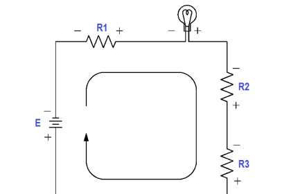
The megger is a portable instrument used to measure insulation resistance. The megger consists of a hand-driven DC generator and a direct reading ohm meter. A simplified circuit diagram of the instrument is shown in below Figure.

The moving element of the ohm meter consists of two coils, A and B, which are rigidly mounted to a pivoted central shaft and are free to rotate over a C-shaped core (below Figure). These coils are connected by means of flexible leads. The moving element may point in any meter position when the generator is not in operation.

As current provided by the hand-driven generator flows through Coil B, the coil will tend to set itself at right angles to the field of the permanent magnet. With the test terminals open, giving an infinite resistance, no current flows in Coil A. Thereby, Coil B will govern the motion of the rotating element, causing it to move to the extreme counter-clockwise position, which is marked as infinite resistance.

Megger Circuit Diagram

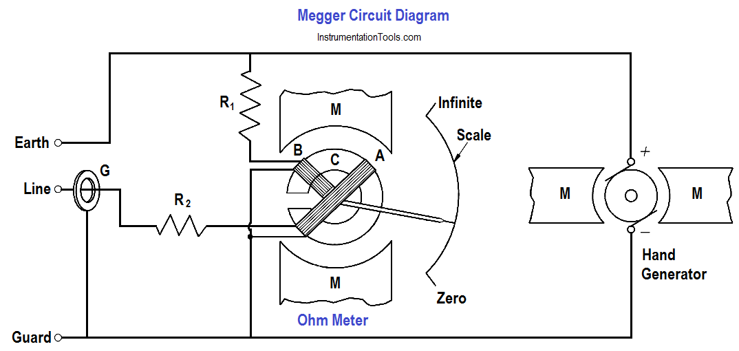
Figure : Simple Megger Circuit Diagram

Coil A is wound in a manner to produce a clockwise torque on the moving element. With the terminals marked “line” and “earth” shorted, giving a zero resistance, the current flow through the Coil A is sufficient to produce enough torque to overcome the torque of Coil B. The pointer then moves to the extreme clockwise position, which is marked as zero resistance. Resistance (R1) will protect Coil A from excessive current flow in this condition.

When an unknown resistance is connected across the test terminals, line and earth, the opposing torques of Coils A and B balance each other so that the instrument pointer comes to rest at some point on the scale. The scale is calibrated such that the pointer directly indicates the value of resistance being measured.

Don't Miss Our Updates
Be the first to get exclusive content straight to your email.
We promise not to spam you. You can unsubscribe at any time.
Invalid email address
You've successfully subscribed !

Continue Reading

Battery Hazards
Resistance in Parallel Circuits
Losses in AC Generator
Series Resistance
Inductive Time Constant
Voltage Divider
Share This Article
Facebook Whatsapp Whatsapp LinkedIn Copy Link
Share
Leave a Comment

Leave a Reply Cancel reply

Your email address will not be published. Required fields are marked *

Stay Connected

128.3kFollowersLike
69.1kFollowersFollow
210kSubscribersSubscribe
38kFollowersFollow

Categories

Explore More

Magnetism
Magnetic Circuits
Discharge and Charging of Lead-Acid Battery
Unbalanced 3 Phase Loads
AC Generator Nameplate Ratings
Capacitance
Moving Iron Vane Meter Movement
What is a circuit breaker ?

Keep Learning

Induction Motor Torque

AC Induction Motor Slip

Generator Action in a Motor

Generator Action in a Motor

Transformer Efficiency

Transformer Efficiency

Parallel RLC Circuit

Impedance in RLC Circuits

Block Diagram

Block Diagram

Types of Capacitors

Types of Capacitors

Transformer Efficiency and Loses Formula

Transformer Losses and Efficiency

Battery Interview QuBattery Interview Question and Answersestion and Answers

Battery Terminology

Learn More

Unmanaged Switch

Managed Switch vs Unmanaged Switch

HART-IP Principle

What is HART- IP ?

Instrumentation Design Engineer

Role of an Instrumentation Design Engineer for Beginners

Fire Pump

What is a Fire Pump? – Definition, Principle, Types, Comparison

Electrical and Instrumentation Maintenance Test

Electrical and Instrumentation Test

relationship between resistance, reactance, and impedance

Impedance

FIFO and LIFO Sequences in PLC

What are FIFO and LIFO Sequences in PLC?

What is a Lightning Arrester? How does it work?

Menu

  • About
  • Privacy Policy
  • Copyright

Quick Links

  • Learn PLC
  • Helping Hand
  • Part Time Job

YouTube Subscribe

Follow US
All rights reserved. Reproduction in whole or in part without written permission is prohibited.
Welcome Back!

Sign in to your account

Username or Email Address
Password

Lost your password?