Inst ToolsInst ToolsInst Tools
  • Courses
  • Automation
    • PLC
    • Control System
    • Safety System
    • Communication
    • Fire & Gas System
  • Instrumentation
    • Design
    • Pressure
    • Temperature
    • Flow
    • Level
    • Vibration
    • Analyzer
    • Control Valve
    • Switch
    • Calibration
    • Erection & Commissioning
  • Interview
    • Instrumentation
    • Electrical
    • Electronics
    • Practical
  • Q&A
    • Instrumentation
    • Control System
    • Electrical
    • Electronics
    • Analog Electronics
    • Digital Electronics
    • Power Electronics
    • Microprocessor
Search
  • Books
  • Software
  • Projects
  • Process
  • Tools
  • Basics
  • Formula
  • Power Plant
  • Root Cause Analysis
  • Electrical Basics
  • Animation
  • Standards
  • 4-20 mA Course
  • Siemens PLC Course
Reading: Instrumentation Symbols Legend
Share
Notification Show More
Font ResizerAa
Inst ToolsInst Tools
Font ResizerAa
  • Courses
  • Design
  • PLC
  • Interview
  • Control System
Search
  • Courses
  • Automation
    • PLC
    • Control System
    • Safety System
    • Communication
    • Fire & Gas System
  • Instrumentation
    • Design
    • Pressure
    • Temperature
    • Flow
    • Level
    • Vibration
    • Analyzer
    • Control Valve
    • Switch
    • Calibration
    • Erection & Commissioning
  • Interview
    • Instrumentation
    • Electrical
    • Electronics
    • Practical
  • Q&A
    • Instrumentation
    • Control System
    • Electrical
    • Electronics
    • Analog Electronics
    • Digital Electronics
    • Power Electronics
    • Microprocessor
Follow US
All rights reserved. Reproduction in whole or in part without written permission is prohibited.
Inst Tools > Blog > Basics > Instrumentation Symbols Legend

Instrumentation Symbols Legend

Last updated: April 2, 2019 6:29 pm
Editorial Staff
Basics
1 Comment
Share
1 Min Read
SHARE

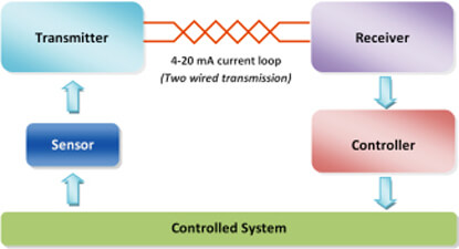
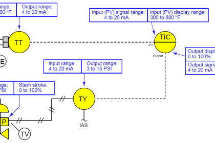
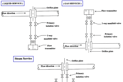
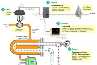
Piping and Instrumentation Diagrams (P&IDs) use specific symbols to show the connectivity of equipment, sensors, and valves in a control system.

These symbols can represent actuators, sensors, and controllers and may be apparent in most, if not all, system diagrams.

P&IDs provide more detail than a process flow diagram with the exception of the parameters, i.e. temperature, pressure, and flow values. “Process equipment, valves, instruments and pipe lines are tagged with unique identification codes.

Common P&ID Symbols Legend

Piping and instrumentation diagrams, or P&IDs, are used to create important documentation for process industry facilities.

The shapes in this legend are representative of the functional relationship between piping, instrumentation, and system equipment units. We’ve broken them down into seven main groups: equipment, piping, vessels, heat exchangers, pumps, instruments, and valves.

Process and Instrumentation Diagrams use special shapes to represent different types of equipment’s, valves, instruments and pipelines.
Also Read : Basics of Instrumentation Engineering
Don't Miss Our Updates
Be the first to get exclusive content straight to your email.
We promise not to spam you. You can unsubscribe at any time.
Invalid email address
You've successfully subscribed !

Continue Reading

Control and Instrumentation Engineer Study Guide
Troubleshooting a 4-20mA Current loop
Difference between PFD and P&ID with Example
4-20 mA Transmitter Wiring Types : 2-Wire, 3-Wire, 4-Wire
How a 4-20mA Transmitter Works?
Understanding a Process Control Loop
Share This Article
Facebook Whatsapp Whatsapp LinkedIn Copy Link
Share
1 Comment
  • Nyl says:
    August 7, 2015 at 11:39 pm

    Great sources. No doubt, you’re an authority in the industry.

    Reply

Leave a Reply Cancel reply

Your email address will not be published. Required fields are marked *

Stay Connected

128.3kFollowersLike
69.1kFollowersFollow
208kSubscribersSubscribe
38kFollowersFollow

Categories

Explore More

Process Control Instrumentation Glossary
Basics of 4 to 20 mA analog Signals
Basics of Valves
Difference between Smart Transmitter and Ordinary Transmitter
Smart Sensors in Industry – Components, Types, Advantages
What are Pre-Shutdown, Shutdown, and Post-Shutdown?
Performance Characteristics of Sensors and Transducers
Impulse Piping standards for Field instruments

Keep Learning

Difference between Analog Signal and Digital Signal

What are Analog and Digital Signals? Differences, Examples

Calculating Loop Voltage Drop

Instrument Cable Voltage Drop

Formulas to calculate ma from PV

Formulas to calculate mA from PV, LRV and URV

Current to Voltage Conversion Circuit

How to Convert Current to Voltage using Resistor ?

GuideLines for Loop Checks

How to Do Loop Checks During Plant Pre-Commissioning

Difference Between Sensor and Transducer

What is the Difference Between Sensor and Transducer?

Electrical Conduit

What is Electrical Conduit? Types, Advantages, Disadvantages

SMART Transmitter

What is a SMART Transmitter?

Learn More

Brass Cable Gland

How to Choose a Brass Cable Gland Manufacturer?

Thermocouple Temperature Ranges

Thermocouple Temperature Range Questions and Answers

Proportional Band example

Why Offset in Proportional Controller ?

What is an Electromechanical Relay

Difference Between Solid State Relay and Electromechanical Relay

Transmission and Distribution Interview Questions

Measurement and Instrumentation Objective Questions – Part 3

Loop Powered Pressure Transmitter

Loop Powered Pressure Transmitter

Why Fire and Gas Detectors are 3-Wire types instead of 2 Wire

Why Fire and Gas Detectors are 3-Wire types instead of 2 Wire?

Air Pre-heater

What is an Air Pre-heater? – Types, Working, Advantages

Follow US
All rights reserved. Reproduction in whole or in part without written permission is prohibited.
Welcome Back!

Sign in to your account

Username or Email Address
Password

Lost your password?