Inst ToolsInst ToolsInst Tools
  • Courses
  • Automation
    • PLC
    • Control System
    • Safety System
    • Communication
    • Fire & Gas System
  • Instrumentation
    • Design
    • Pressure
    • Temperature
    • Flow
    • Level
    • Vibration
    • Analyzer
    • Control Valve
    • Switch
    • Calibration
    • Erection & Commissioning
  • Interview
    • Instrumentation
    • Electrical
    • Electronics
    • Practical
  • Q&A
    • Instrumentation
    • Control System
    • Electrical
    • Electronics
    • Analog Electronics
    • Digital Electronics
    • Power Electronics
    • Microprocessor
  • Request
Search
  • Books
  • Software
  • Projects
  • Process
  • Tools
  • Basics
  • Formula
  • Power Plant
  • Root Cause Analysis
  • Electrical Basics
  • Animation
  • Standards
  • 4-20 mA Course
  • Siemens PLC Course
Reading: How a Bourdon Tube Pressure Gauge might be Adjusted for Linearity?
Share
Notification Show More
Font ResizerAa
Inst ToolsInst Tools
Font ResizerAa
  • Courses
  • Design
  • PLC
  • Interview
  • Control System
Search
  • Courses
  • Automation
    • PLC
    • Control System
    • Safety System
    • Communication
    • Fire & Gas System
  • Instrumentation
    • Design
    • Pressure
    • Temperature
    • Flow
    • Level
    • Vibration
    • Analyzer
    • Control Valve
    • Switch
    • Calibration
    • Erection & Commissioning
  • Interview
    • Instrumentation
    • Electrical
    • Electronics
    • Practical
  • Q&A
    • Instrumentation
    • Control System
    • Electrical
    • Electronics
    • Analog Electronics
    • Digital Electronics
    • Power Electronics
    • Microprocessor
  • Request
Follow US
All rights reserved. Reproduction in whole or in part without written permission is prohibited.
Inst Tools > Blog > Practical Questions > How a Bourdon Tube Pressure Gauge might be Adjusted for Linearity?

How a Bourdon Tube Pressure Gauge might be Adjusted for Linearity?

Last updated: June 3, 2020 4:56 pm
Editorial Staff
Practical Questions
No Comments
Share
3 Min Read
SHARE

A pressure gauge is supposed to accurately indicate applied pressure over its full calibrated range.

Bourdon Tube Pressure Gauge

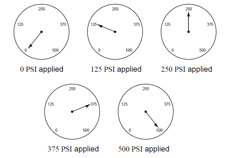
In this example, a gauge with a range of 0 to 500 PSI is subjected to five different pressures along that range, and its response is accurate at all those points:

Pressure gauge is subjected to five different pressures

Describe, by drawing a set of five meter readings such as the set shown above, how a pressure gauge accurate at 0% and 100% of applied pressure – but with a nonlinearity problem between the LRV and URV points – might respond to the same five applied pressures.

Furthermore, describe how a bourdon tube pressure gauge instrument might be adjusted for linearity. In other words, how may a non-linear pressure gauge be calibrated to become more linear?

Answer:

Here is one example of how a pressure gauge might respond in a non-linear fashion to the same five applied pressures, while still being accurate at the LRV and URV points:

non-linear pressure gauge

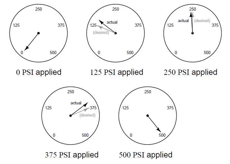
Here, the gauge reads high at the 25% point (125 PSI), slightly low at the 50% point (250 PSI), and low at the 75% point (375 PSI), while still accurate at 0% (0 PSI) and 100% (500 PSI).

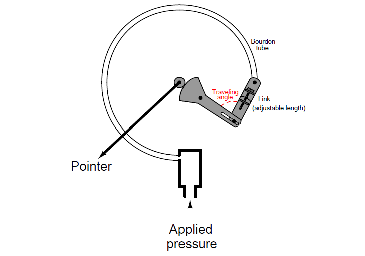
Any adjustment that affects the traveling angle of the mechanism will have an effect on linearity.

Some (high-quality) pressure gauge mechanisms are equipped with an adjustable-length link to facilitate changes to this angle:

Traveling angle of Bourdon Tube

It is sage advice to leave all angle adjustment(s) untouched until all possible zero and span adjustments have been made to the instrument. Usually, it is possible to get a non-linear instrument to read within specified tolerance in a 5-point calibration just by adjusting the zero and span adjustments.

In many mechanical instruments, a simple linearity alignment is to apply a 50% input signal and check for link/lever perpendicularity (that all links and levers intersect at 90o angles to each other).

Questions For You:

Explain how keeping both “As-Found” and “As-Left” calibration records on instruments such as this pressure gauge make it possible to track long-term calibration drift.

Can a non-linearity error be corrected by adjusting the zero and/or span screws on an instrument? Why or why not?

Share your answers with us through below comments section.

Read Next:

  • Instrument Percent of Span Error
  • Displacer Interface Level
  • Calibration of Level Transmitter
  • Circular Chart Recorder Calibration
  • Current-to-Pressure Transducer

Credits: Tony R. Kuphaldt

Don't Miss Our Updates
Be the first to get exclusive content straight to your email.
We promise not to spam you. You can unsubscribe at any time.
Invalid email address
You've successfully subscribed !

Continue Reading

Solenoid Valves Questions & Answers – 4
Re-calibrate the Foxboro DP Pneumatic Transmitter
Practical Process Control System Questions & Answers – 4
Instrument Salesperson Question
Calculate PSV Lift Pressure
Resistance Temperature Detector (RTD) Questions – 1
Share This Article
Facebook Whatsapp Whatsapp LinkedIn Copy Link
Share
Leave a Comment

Leave a Reply Cancel reply

Your email address will not be published. Required fields are marked *

Stay Connected

128.3kFollowersLike
69.1kFollowersFollow
210kSubscribersSubscribe
38kFollowersFollow

Categories

Explore More

Displacer Type Density Transmitter Question
pH Monitoring System Triggers an Alarm
Pneumatic Level Transmitter Calibration Table
What is the Purpose of Bourdon Tube Gauge Spiral Spring?
Define Normal Status for each of the Process Switch
Hydrostatic Pressure Measurement Questions
Identify Instrumentation Terms in Water Supply System
Programmable Logic Controller (PLC) Questions and Answers – 11

Keep Learning

Thermocouple measurement and reference junction temperatures

Thermocouple Measurement and Reference Junction Temperatures

Questions on Pneumatic Control Loop

Questions on Pneumatic Control Loop

Electric-driven Air Compressor Troubleshooting

Electric-driven Air Compressor Troubleshooting

Solenoid Valves Questions

Solenoid Valves Questions & Answers – 3

Stripper Overhead Temperature Control

Stripper Overhead Temperature Control System

Programmable Logic Controller (PLC) Questions and Answers

Programmable Logic Controller (PLC) Questions and Answers – 1

Two pressure switches

Identify Two Pressure Switches Logic

PLC Program

Example PLC Program

Learn More

PLC Timer Application in Security Camera Recording

PLC Timer Application in Security Camera Recording

Closed-tank-DP-Level-Transmitter-with-wet-leg-Zero-elevation-Calibration

Closed tank DP Level Transmitter with wet leg Zero elevation Calibration

dissolved-oxygen-probe-calibration-procedure

Dissolved oxygen probe calibration procedure

Electrical Machines Questions and Answers

Electrical Machines Questions and Answers

Split-Range, Auto-Selector Ratio, And Cascade Systems

Split-Range, Auto-Selector, Ratio & Cascade Systems

Twisted Pair Cable Noise Supression

Why We use Shielded Cable and Twisted Pair Cables ?

Basics of Thermistors, Thermocouples and RTD's

Basics of Thermistors, Thermocouples and RTD’s

Basic Temperature Sensors MCQ

Basic Temperature Sensors MCQ Questions Answers

Menu

  • About
  • Privacy Policy
  • Copyright

Quick Links

  • Learn PLC
  • Helping Hand
  • Part Time Job

YouTube Subscribe

Follow US
All rights reserved. Reproduction in whole or in part without written permission is prohibited.
Welcome Back!

Sign in to your account

Username or Email Address
Password

Lost your password?