Inst ToolsInst ToolsInst Tools
  • Courses
  • Automation
    • PLC
    • Control System
    • Safety System
    • Communication
    • Fire & Gas System
  • Instrumentation
    • Design
    • Pressure
    • Temperature
    • Flow
    • Level
    • Vibration
    • Analyzer
    • Control Valve
    • Switch
    • Calibration
    • Erection & Commissioning
  • Interview
    • Instrumentation
    • Electrical
    • Electronics
    • Practical
  • Q&A
    • Instrumentation
    • Control System
    • Electrical
    • Electronics
    • Analog Electronics
    • Digital Electronics
    • Power Electronics
    • Microprocessor
Search
  • Books
  • Software
  • Projects
  • Process
  • Tools
  • Basics
  • Formula
  • Power Plant
  • Root Cause Analysis
  • Electrical Basics
  • Animation
  • Standards
  • 4-20 mA Course
  • Siemens PLC Course
Reading: PLC Program for Automatic Parameter Initialization When Power UP
Share
Notification Show More
Font ResizerAa
Inst ToolsInst Tools
Font ResizerAa
  • Courses
  • Design
  • PLC
  • Interview
  • Control System
Search
  • Courses
  • Automation
    • PLC
    • Control System
    • Safety System
    • Communication
    • Fire & Gas System
  • Instrumentation
    • Design
    • Pressure
    • Temperature
    • Flow
    • Level
    • Vibration
    • Analyzer
    • Control Valve
    • Switch
    • Calibration
    • Erection & Commissioning
  • Interview
    • Instrumentation
    • Electrical
    • Electronics
    • Practical
  • Q&A
    • Instrumentation
    • Control System
    • Electrical
    • Electronics
    • Analog Electronics
    • Digital Electronics
    • Power Electronics
    • Microprocessor
Follow US
All rights reserved. Reproduction in whole or in part without written permission is prohibited.
Inst Tools > Blog > Guest Articles > PLC Program for Automatic Parameter Initialization When Power UP

PLC Program for Automatic Parameter Initialization When Power UP

Due to power failure, PLC parameter values becomes zero. Write a PLC Program for Automatic Parameter Initialization when Power UP.

Last updated: November 3, 2023 10:12 am
Editorial Staff
Guest Articles PLC Tutorials
1 Comment
Share
4 Min Read
SHARE

This is a PLC Program for Automatic Parameter initialization when power up.

Contents
Parameter Initialization When Power UPProblem DiagramProblem SolutionPLC Ladder diagramInputs ListOutputs ListProgram DescriptionRuntime Test Cases

Parameter Initialization When Power UP

Problem Description

In many applications, it is necessary to initialize some data when the machine is powered up.

Sometimes due to power failure, the value in some parameters becomes zero.

Due to this problem, the operator has to feed all data again or every time during power failure.

When the machine gets powered up, at that time necessary parameters should be initialized automatically.

Here we discuss this issue with some basic ladder logic.

Problem Diagram
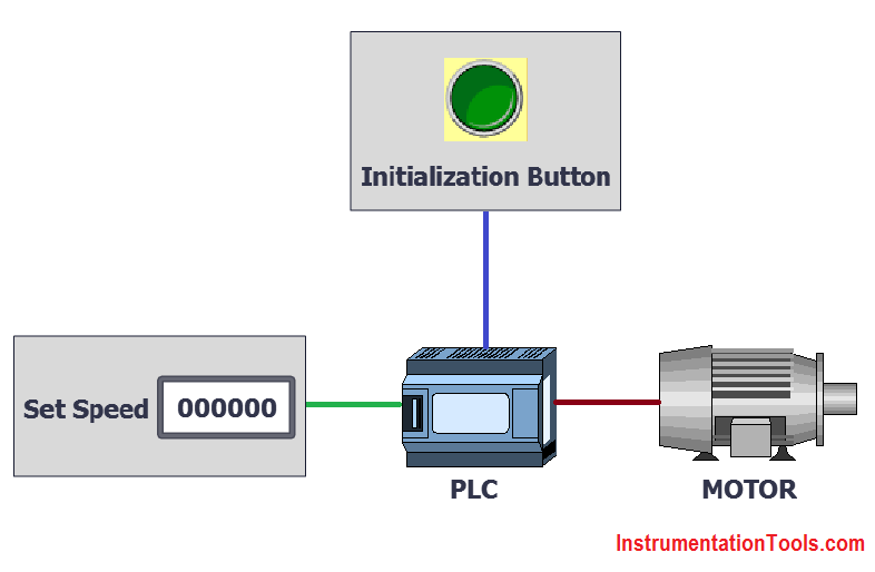
PLC Program for Automatic Parameter initialization

Problem Solution

In this case, we need to write the logic in the PLC program so all parameters will be initialized automatically.

We can also set a manual initialization button so the operator can initialize data while the machine operation is running.

Here we will consider the machine set speed as data and it will be initialized automatically when the machine turns on.

If the operator wants to reinitialize the set speed during the running cycle then he needs to do it through the initialization button.

PLC Ladder diagram

Here is the PLC program Automatic Parameter initialization when powered up.
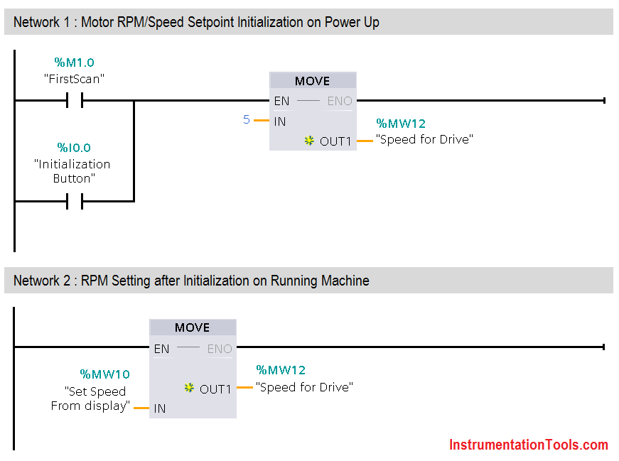
PLC Parameter Initialization

List of PLC inputs/outputs

Inputs List

  • Parameter Initialization Button : I0.0
  • MW10 : Set Speed form Display

Outputs List

  • Mw12 : Speed for drive

Program Description

  • For this application we use S7-1200 PLC and TIA portal software for programming.
  • This logic is used for parameter initialization.
  • For first scan, we used here S7-1200 facilities of system Memory. Every PLC have its own system memory.
  • Always ON bit, always OFF bit, first scan bit, and diagnostic status changed are the system memory for S7-1200 PLC.
  • We can configure any memory address “M” for system memory. Here we configured M1.0 for first scan bit which is used for parameter initialization.
  • We write for parameter initialization in Network 1. Here we use NO contact of First scan bit (M1.0) for moving initial 5 RPM in MW12(Speed for drive).By using MOVE instruction 5 RPM will be moved in MW12 . Add NO contact of Parameter Initialization Button (I0.0) for moving Initial 5RPM in MW12 (Speed for drive) manually.
  • For editing data manually in running cycle we write logic in Network 2. Here operator can enter data in MW10 (SET SPEED) from the display and it will go in MW12(Speed for drive).
  • For Example, Say we need to enter 100 RPM speed from display it will be written in word MW10 (Set Speed from display) and as per logic it will be moved in MW12 (Speed for drive), so motor will run on 100 RPM.

Runtime Test Cases

plc program automatic parameters

Note: The above PLC Logic provided for basic idea about application of PLC Program for Automatic Parameter Initialization when Power UP. The Logic is limited and not complete application.

Author: Bhavesh

If you liked this article, then please subscribe to our YouTube Channel for PLC and SCADA video tutorials.

You can also follow us on Facebook and Twitter to receive daily updates.

Read Next:

  • PLC Separate Different Size Objects
  • Automatic Empty Bottle detection using PLC
  • PLC Program for Paint Spraying
  • Siemens PLC configuration in TIA Portal
  • PLC Selective Execution of the Application
Don't Miss Our Updates
Be the first to get exclusive content straight to your email.
We promise not to spam you. You can unsubscribe at any time.
Invalid email address
You've successfully subscribed !

Continue Reading

Traffic Lights Ladder Diagram using Timers
What is Loop Checking?
Types of Failures in Industrial Automation Systems
Basics of Fail-safe Circuits
Types of Instructions in PLC Programming
Using of MCT instead of Cable Glands on the Cabinets
Share This Article
Facebook Whatsapp Whatsapp LinkedIn Copy Link
Share
1 Comment
  • mukesh khurse says:
    November 18, 2021 at 1:32 pm

    Sir please make artical about loadcell ladder logic programing how to program and calibration.

    Reply

Leave a Reply Cancel reply

Your email address will not be published. Required fields are marked *

Stay Connected

128.3kFollowersLike
69.1kFollowersFollow
208kSubscribersSubscribe
38kFollowersFollow

Categories

Explore More

Learn about PLC, DCS, RTU, SCADA, and PAC
Shutter Door Control using Motor and Limit Switches
UPS Working Principle and Types – Offline and Online UPS Systems
PLC based Metro Automation Project
PLC Program for Ceramic Burning Oven Conveyor System
How to Install GSD File in Step 7 PLC using Simatic Manager?
Design a Program Using Studio 5000 and FactoryTalk View Studio
PLC Programming Example on Bottle Line Control

Keep Learning

PLC Subroutine

Allen Bradley PLC Subroutines

Automatic Box Filling System using PLC Programming

Automatic Box Filling System using PLC Programming

Marking Machine

PLC SCL Program for Marking Machine

Programmable Logic Controller Quiz

Programmable Logic Controller Quiz

Save and BR Memory in Siemens PLC Programming

SAVE and BR Memory Instructions in Siemens PLC Programming

User Defined Function Blocks in PLC

What are User Defined Function Blocks in PLC?

How to Filter Digital and Analog Inputs in a PLC

How to Filter Digital and Analog Inputs in a PLC?

Difference Between Industrial Computer and Normal Computer

Difference Between Industrial Computer (IPC) and Normal Computer (PC)

Learn More

Analog inputs in library

Design Process Graphics in Factory Talk View Studio with an Analog Input

Digital Electronics Multiple Choice Questions

Introduction of Arithmetic Operation

Valve Cv Rating Calculator

Pneumatic Cylinder & Valve Sizing Calculator

Instrument Percent of Span Error

Instrument Percent of Span Error

Instrumentation loop Diagram

Instrumentation Loop Diagrams

Paddle switch Working Principle

Paddle Switch Working Principle

Online Simulation

Infrared Open Path Gas Detectors Operation

Infrared Open Path Gas Detectors Working Principle

Follow US
All rights reserved. Reproduction in whole or in part without written permission is prohibited.
Welcome Back!

Sign in to your account

Username or Email Address
Password

Lost your password?