This is a PLC Program for the selective execution of the application.
Selective Execution of an Application
Problem Description
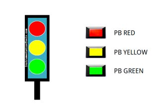
There are pigments of three colors. We need to fill different pigments into the jar by selecting the selector switches.
Implement the PLC program using a ladder programming language.
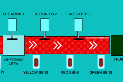
Problem Diagram

Problem Solution
In this system, we will consider S7-300 PLC and TIA portal software for programming.
Here we need to fill different pigments in the jar as per requirement. So consider 3 types of different color pigments (Yellow, blue, and green.).
Two valves are used for controlling the pigments. (As we know mixing of yellow and blue is green color so there is no need of separate valve for green color.)
When both yellow and blue color are filled at the same time, it will become green color. Selector switch is used for color selection in the system and ON/OFF switch is used for system STOP.
List of Inputs/Outputs
Inputs List
- ON/OFF :- I2.0
- START PB :- I0.0
- STOP PB :- I0.1
- Yellow pigment selection :- I0.2
- Blue pigment selection :- I0.3
- Green pigment selection :- I0.4
Outputs List
- Cycle ON :- Q0.0
- Yellow control valve :- Q0.1
- Blue control valve :- Q0.2
Ladder Diagram for Selective Execution of the Application
Program Description
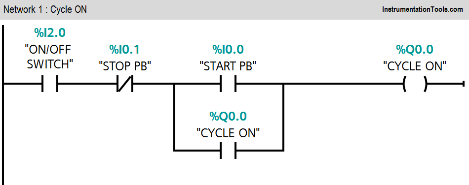
Network 1
When ON/OFF switch (I2.0) is ON and START PB is pressed, Cycle ON (Q0.0) lamp will be ON.
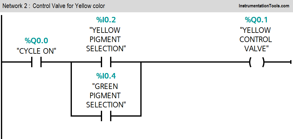
Network 2
If cycle is ON and yellow color pigment is selected (I0.2), yellow color control valve (Q0.1) will be ON.
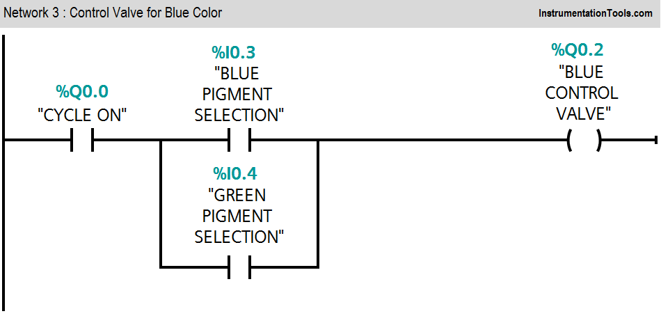
Network 3
If cycle is ON and blue color pigment is selected (I0.3), blue color control valve (Q0.2) will be ON. If green color pigment is selected (I0.4), both the valves will be ON and pigment will become green color.
Result

Author: Bhavesh
If you liked this article, then please subscribe to our YouTube Channel for PLC and SCADA video tutorials.
You can also follow us on Facebook and Twitter to receive daily updates.
Read Next:
- PLC Control Valve Scaling
- Split Range Control Application using PLC
- Opposite Acting Control Valves using PLC
- Siemens S7 1200 PLC configuration in TIA Portal
- PLC Program for Paint Spraying