Inst ToolsInst ToolsInst Tools
  • Courses
  • Automation
    • PLC
    • Control System
    • Safety System
    • Communication
    • Fire & Gas System
  • Instrumentation
    • Design
    • Pressure
    • Temperature
    • Flow
    • Level
    • Vibration
    • Analyzer
    • Control Valve
    • Switch
    • Calibration
    • Erection & Commissioning
  • Interview
    • Instrumentation
    • Electrical
    • Electronics
    • Practical
  • Q&A
    • Instrumentation
    • Control System
    • Electrical
    • Electronics
    • Analog Electronics
    • Digital Electronics
    • Power Electronics
    • Microprocessor
  • Request
Search
  • Books
  • Software
  • Projects
  • Process
  • Tools
  • Basics
  • Formula
  • Power Plant
  • Root Cause Analysis
  • Electrical Basics
  • Animation
  • Standards
  • 4-20 mA Course
  • Siemens PLC Course
Reading: PLC Program for Automatic Parameter Initialization When Power UP
Share
Notification Show More
Font ResizerAa
Inst ToolsInst Tools
Font ResizerAa
  • Courses
  • Design
  • PLC
  • Interview
  • Control System
Search
  • Courses
  • Automation
    • PLC
    • Control System
    • Safety System
    • Communication
    • Fire & Gas System
  • Instrumentation
    • Design
    • Pressure
    • Temperature
    • Flow
    • Level
    • Vibration
    • Analyzer
    • Control Valve
    • Switch
    • Calibration
    • Erection & Commissioning
  • Interview
    • Instrumentation
    • Electrical
    • Electronics
    • Practical
  • Q&A
    • Instrumentation
    • Control System
    • Electrical
    • Electronics
    • Analog Electronics
    • Digital Electronics
    • Power Electronics
    • Microprocessor
  • Request
Follow US
All rights reserved. Reproduction in whole or in part without written permission is prohibited.
Inst Tools > Blog > Guest Articles > PLC Program for Automatic Parameter Initialization When Power UP

PLC Program for Automatic Parameter Initialization When Power UP

Due to power failure, PLC parameter values becomes zero. Write a PLC Program for Automatic Parameter Initialization when Power UP.

Last updated: November 3, 2023 10:12 am
Editorial Staff
Guest Articles PLC Tutorials
1 Comment
Share
4 Min Read
SHARE

This is a PLC Program for Automatic Parameter initialization when power up.

Contents
Parameter Initialization When Power UPProblem DiagramProblem SolutionPLC Ladder diagramInputs ListOutputs ListProgram DescriptionRuntime Test Cases

Parameter Initialization When Power UP

Problem Description

In many applications, it is necessary to initialize some data when the machine is powered up.

Sometimes due to power failure, the value in some parameters becomes zero.

Due to this problem, the operator has to feed all data again or every time during power failure.

When the machine gets powered up, at that time necessary parameters should be initialized automatically.

Here we discuss this issue with some basic ladder logic.
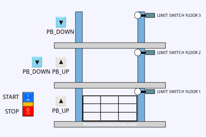
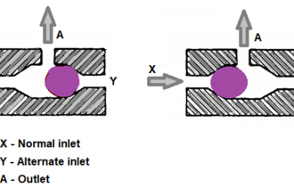
Problem Diagram

PLC Program for Automatic Parameter initialization

Problem Solution

In this case, we need to write the logic in the PLC program so all parameters will be initialized automatically.

We can also set a manual initialization button so the operator can initialize data while the machine operation is running.

Here we will consider the machine set speed as data and it will be initialized automatically when the machine turns on.

If the operator wants to reinitialize the set speed during the running cycle then he needs to do it through the initialization button.
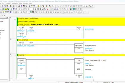
PLC Ladder diagram

Here is the PLC program Automatic Parameter initialization when powered up.

PLC Parameter Initialization

List of PLC inputs/outputs

Inputs List

  • Parameter Initialization Button : I0.0
  • MW10 : Set Speed form Display

Outputs List

  • Mw12 : Speed for drive

Program Description

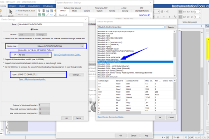
  • For this application we use S7-1200 PLC and TIA portal software for programming.
  • This logic is used for parameter initialization.
  • For first scan, we used here S7-1200 facilities of system Memory. Every PLC have its own system memory.
  • Always ON bit, always OFF bit, first scan bit, and diagnostic status changed are the system memory for S7-1200 PLC.
  • We can configure any memory address “M” for system memory. Here we configured M1.0 for first scan bit which is used for parameter initialization.
  • We write for parameter initialization in Network 1. Here we use NO contact of First scan bit (M1.0) for moving initial 5 RPM in MW12(Speed for drive).By using MOVE instruction 5 RPM will be moved in MW12 . Add NO contact of Parameter Initialization Button (I0.0) for moving Initial 5RPM in MW12 (Speed for drive) manually.
  • For editing data manually in running cycle we write logic in Network 2. Here operator can enter data in MW10 (SET SPEED) from the display and it will go in MW12(Speed for drive).
  • For Example, Say we need to enter 100 RPM speed from display it will be written in word MW10 (Set Speed from display) and as per logic it will be moved in MW12 (Speed for drive), so motor will run on 100 RPM.

Runtime Test Cases

plc program automatic parameters

Note: The above PLC Logic provided for basic idea about application of PLC Program for Automatic Parameter Initialization when Power UP. The Logic is limited and not complete application.

Author: Bhavesh

If you liked this article, then please subscribe to our YouTube Channel for PLC and SCADA video tutorials.

You can also follow us on Facebook and Twitter to receive daily updates.

Read Next:

  • PLC Separate Different Size Objects
  • Automatic Empty Bottle detection using PLC
  • PLC Program for Paint Spraying
  • Siemens PLC configuration in TIA Portal
  • PLC Selective Execution of the Application
Don't Miss Our Updates
Be the first to get exclusive content straight to your email.
We promise not to spam you. You can unsubscribe at any time.
Invalid email address
You've successfully subscribed !

Continue Reading

Difference Between PNP and NPN Sensors
Automatic Car Washing using PLC
PLC Ladder Logic for Opposite Acting Control Valves Application
Abbreviations of Pressure, Temperature & Flow
Why Are Charcoal and Salt Added to an Earthing Pit?
Shutter Door Control using Motor and Limit Switches
Share This Article
Facebook Whatsapp Whatsapp LinkedIn Copy Link
Share
1 Comment
  • mukesh khurse says:
    November 18, 2021 at 1:32 pm

    Sir please make artical about loadcell ladder logic programing how to program and calibration.

    Reply

Leave a Reply Cancel reply

Your email address will not be published. Required fields are marked *

Stay Connected

128.3kFollowersLike
69.1kFollowersFollow
210kSubscribersSubscribe
38kFollowersFollow

Categories

Explore More

How to Protect Siemens PLC using Password?
What is a PLC Retrofitting Project? – Importance, Procedure
Smart Automation Solutions: PLC Logic for Stairway Lighting
VFD Simulator Download – Free Yaskawa V1000 Software
PLC Program for Mailbox with Letter Counting & Light Indicators
What is Nest Loading? – DCS and PLC Control Systems
PLC Project Examples for EcoStruxure Machine Expert
Types of Noise in Electronics

Keep Learning

Features of Scada Which are Must in an IoT System

Features of Scada Which are Must in an IoT System

Interlock

Process Interlocks and Trips

PLC Motor Control Circuit

Motor Trip Logic using PLC Programming

How to use Scale and Normalize Instructions in PLC

Scale and Normalize Instructions in PLC

PLC Programming Example with Pushbutton and Motor

PLC Programming Example with Pushbutton and Motor

Introduction to PLC

#9 PLC Best Practices – Validate indirections

Omron PLC for Product Painting with Integrated Weighing System

Omron PLC for Product Painting with Integrated Weighing System

Instrumentation Design Details

I&C Engineer Roles & Responsibilities – Instrumentation Design

Learn More

PLC Example on Manufacturing Line Assembly

PLC Example on Manufacturing Line Assembly

Analog Demodulators Objective Questions

Analog Demodulators Objective Questions

Level Calculation with Remote Seals

Level Calculation with Remote Seals

Serial Communication Error Checking Methods and Algorithms

Serial Communication Error Checking Methods and Algorithms

Resistor Y and Delta Network Calculation

Y and Delta Resistor Network Calculations

DP Transmitter Problem

DP Transmitter Problem

Improved Sprocket Segment Bolting to body

A Plant Bucket Elevators chains too short chain lives problem eliminated

Induction Motor Operating Characteristics

Menu

  • About
  • Privacy Policy
  • Copyright

Quick Links

  • Learn PLC
  • Helping Hand
  • Part Time Job

YouTube Subscribe

Follow US
All rights reserved. Reproduction in whole or in part without written permission is prohibited.
Welcome Back!

Sign in to your account

Username or Email Address
Password

Lost your password?