Inst ToolsInst ToolsInst Tools
  • Courses
  • Automation
    • PLC
    • Control System
    • Safety System
    • Communication
    • Fire & Gas System
  • Instrumentation
    • Design
    • Pressure
    • Temperature
    • Flow
    • Level
    • Vibration
    • Analyzer
    • Control Valve
    • Switch
    • Calibration
    • Erection & Commissioning
  • Interview
    • Instrumentation
    • Electrical
    • Electronics
    • Practical
  • Q&A
    • Instrumentation
    • Control System
    • Electrical
    • Electronics
    • Analog Electronics
    • Digital Electronics
    • Power Electronics
    • Microprocessor
  • Request
Search
  • Books
  • Software
  • Projects
  • Process
  • Tools
  • Basics
  • Formula
  • Power Plant
  • Root Cause Analysis
  • Electrical Basics
  • Animation
  • Standards
  • 4-20 mA Course
  • Siemens PLC Course
Reading: DC Motor Speed
Share
Font ResizerAa
Inst ToolsInst Tools
Font ResizerAa
  • Courses
  • Design
  • PLC
  • Interview
  • Control System
Search
  • Courses
  • Automation
    • PLC
    • Control System
    • Safety System
    • Communication
    • Fire & Gas System
  • Instrumentation
    • Design
    • Pressure
    • Temperature
    • Flow
    • Level
    • Vibration
    • Analyzer
    • Control Valve
    • Switch
    • Calibration
    • Erection & Commissioning
  • Interview
    • Instrumentation
    • Electrical
    • Electronics
    • Practical
  • Q&A
    • Instrumentation
    • Control System
    • Electrical
    • Electronics
    • Analog Electronics
    • Digital Electronics
    • Power Electronics
    • Microprocessor
  • Request
Follow US
All rights reserved. Reproduction in whole or in part without written permission is prohibited.
Inst Tools > Blog > Electrical Theory > DC Motor Speed

DC Motor Speed

Last updated: July 29, 2018 11:43 am
Editorial Staff
Electrical Theory
No Comments
Share
2 Min Read
SHARE

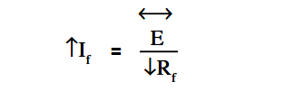
The field of a DC motor is varied using external devices, usually field resistors. For a constant applied voltage to the field (E), as the resistance of the field (Rf) is lowered, the amount of current flow through the field (If) increases as shown by Ohm’s law in below Equation.

DC Motor Speed Equation

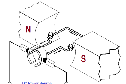
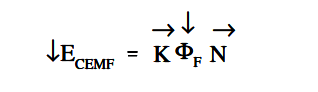
An increase in field current will cause field flux (Φf ) to increase. Conversely, if the resistance of the field is increased, field flux will decrease. If the field flux of a DC motor is decreased, the motor speed will increase. The reduction of field strength reduces the CEMF of the motor, since fewer lines of flux are being cut by the armature conductors, as shown in below Equation.

DC Motor Speed Equation - 1

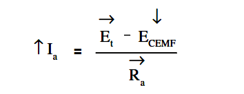
A reduction of counter EMF allows an increase in armature current as shown in below Equation.

DC Motor Speed Equation - 2

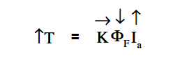
This increase in armature current causes a larger torque to be developed; the increase in armature current more than offsets the decrease in field flux as shown in below Equation.

DC Motor Speed Equation - 3

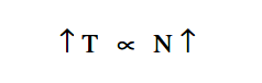
This increased torque causes the motor to increase in speed.

DC Motor Speed Equation - 4

This increase in speed will then proportionately increase the CEMF. The speed and CEMF will continue to increase until the armature current and torque are reduced to values just large enough to supply the load at a new constant speed.

Don't Miss Our Updates
Be the first to get exclusive content straight to your email.
We promise not to spam you. You can unsubscribe at any time.
Invalid email address
You've successfully subscribed !

Continue Reading

Electrical Symbols
What is Synchroscope ?
Batteries
Types of AC Generators
Transformer Coil Polarity
Calculate Power in Series RL Circuit
Share This Article
Facebook Whatsapp Whatsapp LinkedIn Copy Link
Share
Leave a Comment

Leave a Reply Cancel reply

Your email address will not be published. Required fields are marked *

Stay Connected

128.3kFollowersLike
69.1kFollowersFollow
210kSubscribersSubscribe
38kFollowersFollow

Categories

Explore More

Batteries Theory
Inductive Time Constant
Battery Hazards
DC Circuit Analysis Node Equations
Calculate Power in Series RCL Circuit
DC Motor Torque
Capacitance
Inductance and Inductive Reactance

Keep Learning

Left-Hand Rule for Generators

Starting of DC Motors

AC Generator Operation

Losses in AC Generator

Units of Electrical Measurement

Units of Electrical Measurement

Ground Detector Lamp Method Principle

Ground Detector Principle

Ammeter with Shunt

Ammeter

Electric Short Circuit

Electric Circuit : Open & Short Circuits

DC Motor Connections

DC Motor Connections

Using Kirchhoff’s Voltage Law to find Current with one Source

Applying Kirchhoff’s Voltage Law

Learn More

Control Valves - Repeat Actuator Diaphragm Bursts

Control Valves – Repeat Actuator Diaphragm Bursts

Air Release Valve

What is an Air Valve? Purpose, Types, Advantages, Disadvantages

Optimal Control Systems

Output Regulator & the Tracking Problem

mass flowmeters

What is a Thermal Flow Meter?

Properties of Conducting Materials

Resistivity

How to Use Analog Input in Mitsubishi FX3U LOLLETTE PLC

How to Use Analog Input in Mitsubishi FX3U LOLLETTE PLC?

Sample Raw DataSheet for Pressure Calibration

Sample Raw DataSheet for Pressure Calibration

Mass Spectrometer Questions and Answers

Mass Spectrometer Questions & Answers

Menu

  • About
  • Privacy Policy
  • Copyright

Quick Links

  • Learn PLC
  • Helping Hand
  • Part Time Job

YouTube Subscribe

Follow US
All rights reserved. Reproduction in whole or in part without written permission is prohibited.
Welcome Back!

Sign in to your account

Username or Email Address
Password

Lost your password?