Maybe you will be surprised when you know that, Ladder language is not the only used for programming of a PLC device, as the International Electrotechnical Commission IEC organization approved that.
There are five types of languages that can be used to program a PLC device:
- Ladder Logic (LAD)
- Functional Block Diagram (FBD)
- Sequential Functional Chart (SFC)
- Structured Text (ST)
- Instruction List (IL)
As you could see that the Statement List language (STL) is not one of the IEC languages, it is created especially for SIEMENS PLCs, but on the other hand, we will find that STL and IL languages are 95% identical.
There are just a few differences between them both, but in general, if you can use one of them definitely you will be able to use the other one.
Does really, we need to learn STL Language?
As we said above there are five types of PLC languages, and for a PLC programmer, there is no need to be professional at all of them.
At first, you have to learn the LAD language very well as it is the basic one and to be an advanced programmer you have to choose another language to learn it very well, and for the rest, you have just be aware of the basic instruction for them.
STL Language in PLC
So, if you are interested with STL language here is some of its Advantages & Disadvantages:
| Advantages | Disadvantages |
| A statement List is often the quickest way to write your PLC code. Performing more complex operations like loops and jumps and indirect addressing becomes easier in STL. It is really very concise and would really save a lot of networks for you. | It is too hard for debugging the code. It is entirely possible to write STL code but Step-7 will not be able to convert it back to LAD or FBD. |
Please before selecting the project language just ask yourself these two questions:
- which language makes the code easier, and could support the code needs quickly and efficiently?
- Which programming language makes the code more Readable and easier to make later changes or Troubleshoot the machinery faults?
How to build a simple network in STL?
In our first lesson with STL language we will discuss how to perform (AND, OR, NAND, NOR, Assign) instructions using simple examples.
And also, we will convert some of the complicated networks in the LAD language into STL.
AND, AND NOT Instruction
The below instructions are the addressing format of AND and AND NOT instructions in STL language.
Format
A <Bit Address> // this for And
AN <Bit Address> // this for AND NOT
Description
(A) checks whether the state of the addressed bit is “1”, and ANDs the test result with the RLO.
(AN) checks whether the state of the addressed bit is “0”, and ANDs the test result with the RLO.
Note: RLO is the result of logic operation, this Bit is responsible for adding the logic of each network and save it, as that would help to execute the code logic as desired, and it would really help you a lot in debugging.
Example
Here are we have two inputs (I0.0 when it is false make the RLO = 0 and when it is true make the RLO = 1).
And for the other input inputs (I0.1 when it is false make the RLO = 1 and when it is true to make the RLO = 0) these two inputs control an output (Q0.0).
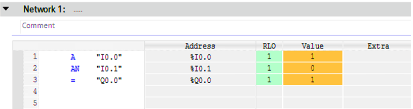
Fig (1)
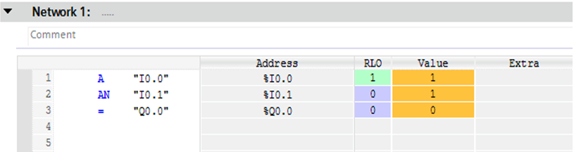
Fig (2)
Here as you can see for Fig (1) the value of I0.0 is one and it is translated into the RLO to one, but for I0.1 when the value is zero it is translated into the RLO to one and vice versa.
Also, you can see in Fig (1) when the RLO is (one) till the end of the network it will assign the Q0.0 to be one, but as shown in Fig (2) the RLO is (one) for just the first line, so Q0.0 would be zero.
OR, OR NOT Instruction
The below instructions are the addressing format of OR and OR NOT instructions in STL language.
Format
O <Bit Address> // this for OR
ON <Bit Address> // this for OR NOT
Description
(O) checks whether the state of the addressed bit is “1”, and ORs the test result with the RLO.
(ON) checks whether the state of the addressed bit is “0”, and ORs the test result with the RLO.
Example
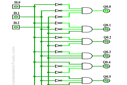
Here is a simple example that shows three different inputs (I0.0 – I0.1 – I0.2) when any one of them is turned to an ON state that would Assign an output (Q0.0).
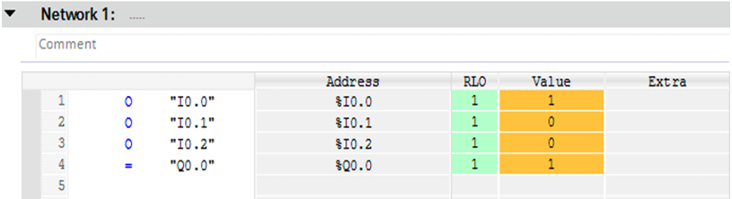
Fig (3)
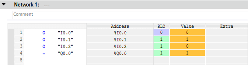
Fig (4)
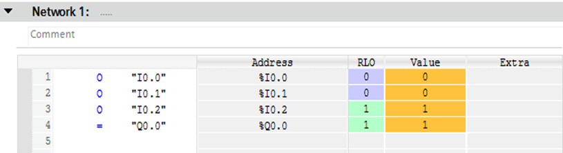
Fig (5)
As we can see in Fig (3,4,5) when any one of the three inputs are turned to be ON the RLO became TRUE and by its role, it turns the output Q0.0 to be ON.
Converting a LAD network into STL language
Finally, and to ensure that you got the idea of the article here is a simple tutorial that illustrates how to convert a complex network of LAD into STL language.
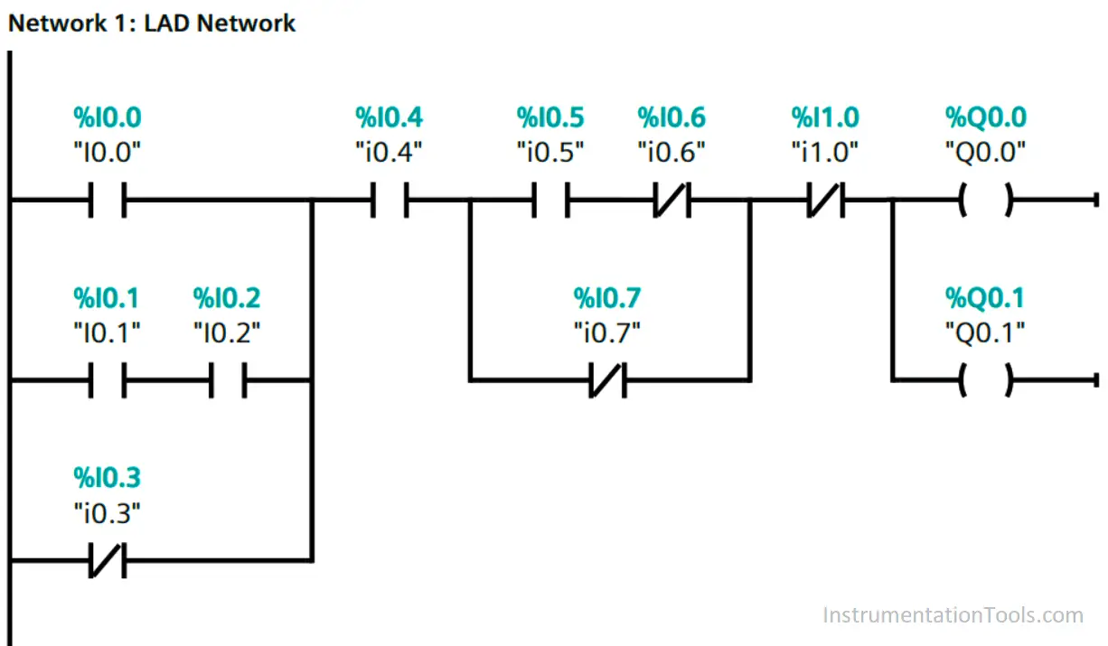
LAD Network
Consider the below ladder logic example.
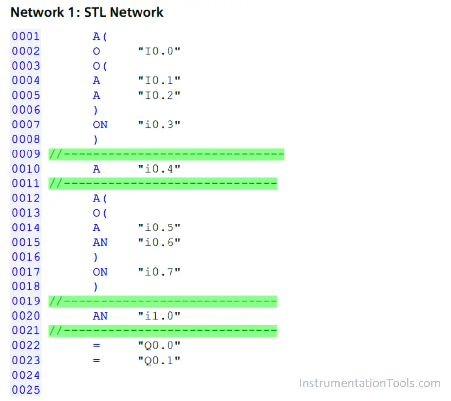
STL Network
The below-mentioned program is the equivalent code of the above ladder logic example.
Video Lesson
In the below video, we explained the simple steps to write an STL program from a ladder logic example.
If you liked this article, then please subscribe to our YouTube Channel for PLC and SCADA video tutorials.
You can also follow us on Facebook and Twitter to receive daily updates.
Read Next:


best artical to clearly understand the baisc concept of STL.
Thank you!
It is use full for bigners.