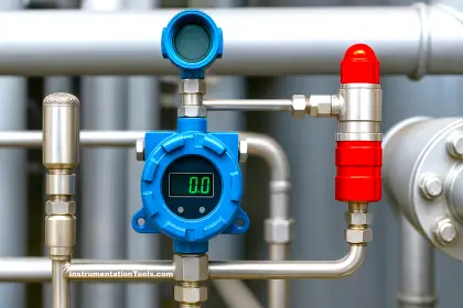
The fixed gas detection system is a sampling system to monitor the gas concentration in a potentially hazardous environment. It is applicable in areas where there is a possible leak of toxic gas and eventual depletion of oxygen.
Examples of application areas are; Boiler plant room, gas bottle storage facility, refineries, oil rigs, etc.
A fixed gas detection system basically constitutes sampling pipes and a detection unit.
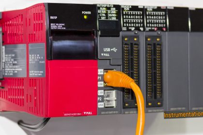
Gas Detection System using PLC
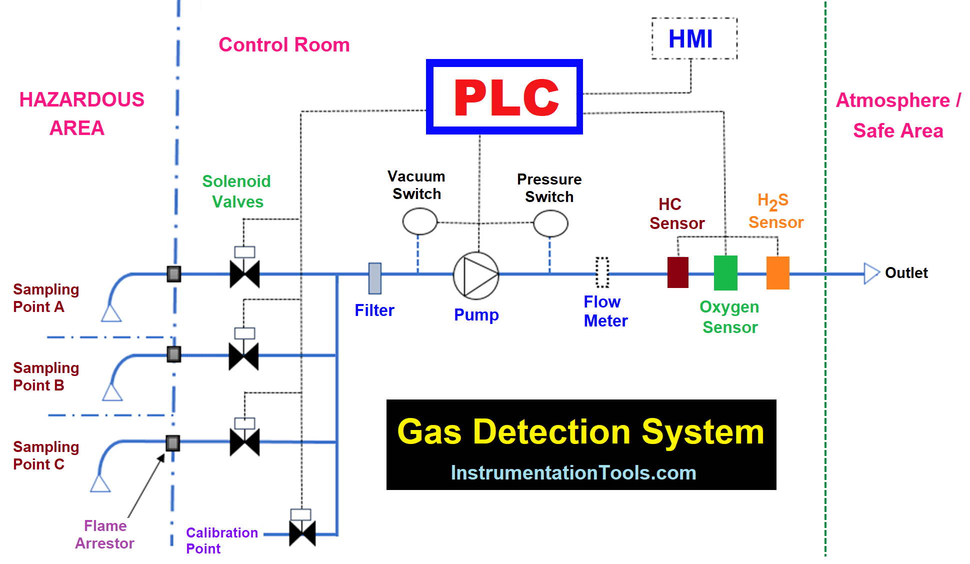
The detection unit contains all the functions for the detection and transport of sample gas.
Its components comprise gas detectors or sensors (oxygen sensor, hydrocarbon sensor, and hydrogen sulfide sensor), solenoid valves, sampling pump, flow meter, PLC, filter, pressure, and vacuum switches.
Gas sample is taken from sample points according to a sampling sequence in the PLC program.
Sample gas is transported through the sampling pipes to the gas detectors where measurement of toxic gas takes place.
Sample gas is filtered to remove dust particles or dirt before it is pumped through the in-line gas sensors to a safe area or atmosphere outside the detection unit.
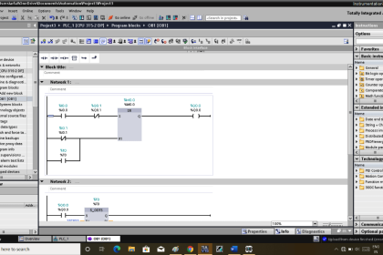
The following PLC ladder program explains the operation of the gas detection system with three (3) sampling points using Siemens CPU 314C-2 DP.
Network 1 – Sampling Pump
One push button (PB) is used to start and stop of sampling pump in input I124.0.
Once the PB is depressed, the set/reset (SR) flip-flop (Q124.0) is set to signal state “1” by the positive signal edge (i.e. change of signal state from “0” to “1”) of the PB at input S.
The output signal state of the SR flip-flop remains at the “1” state so far as the signal state at input R1 has not changed and remains at a “0” state.
Thus, the sampling pump is set to run. When the push button (PB) is pressed once again, the set/reset (SR) flip-flop is set to the “0” state by the negative signal edge (i.e. change of signal state from “1” to “0”) of the PB at input R1 resulting in stopping of sampling pump.
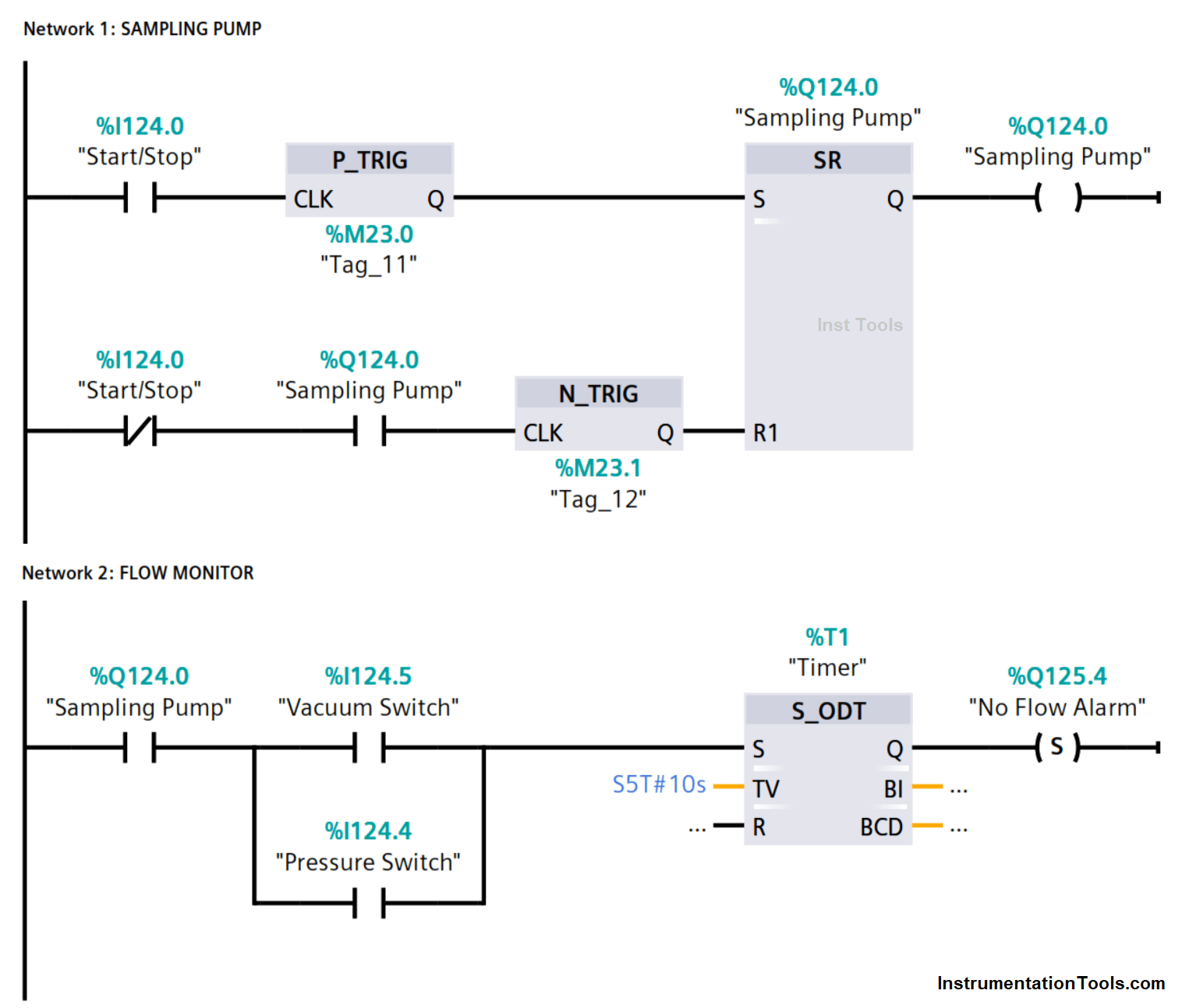
Network 2 – Flow Monitor
Once the sampling pump is running, flow is monitored by the vacuum switch I124.5 and pressure switch I124.4 which are normally open contacts but closes at flow fault condition.
No flow alarm indicates possible failure of sampling pump, choked/dirty filter, or blocked sampling pipe(s).
Delay timer T1 is set to 10 seconds for no flow alarm activation at output Q125.4, and stop of sampling sequence.
Network 3 – No Flow Alarm Reset
Reset of no flow alarm is possible only when alarm buzzer Q125.3 is silenced or deactivated and flow is restored.
Once the flow is restored, vacuum and/or pressure switch contact opens to deactivate timer T1, thus allowing the reset of the no-flow alarm.
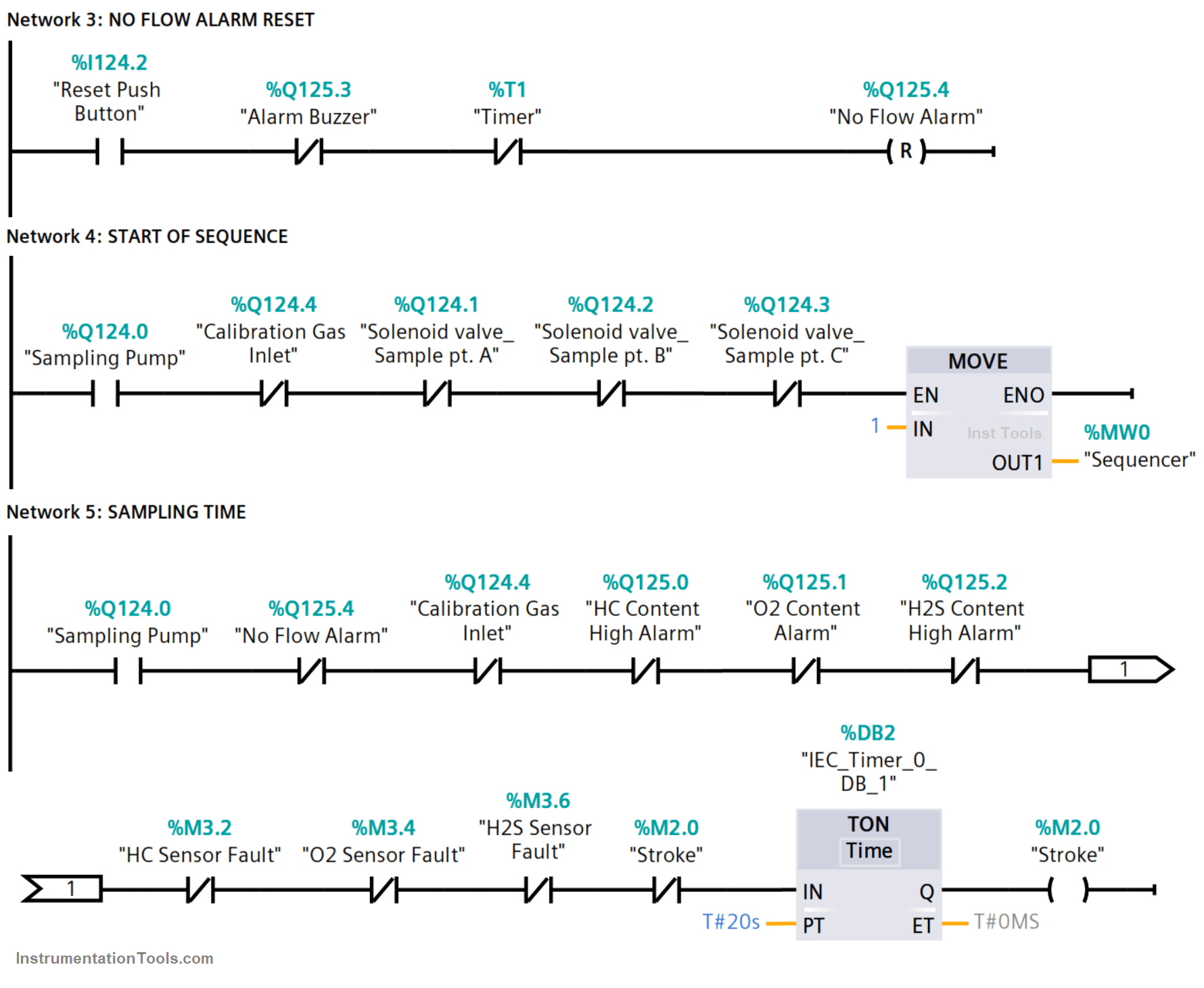
Network 4 – Start of Sequence
The start of the sampling sequence is initiated with a MOVE function.
A bit “1” is moved to memory word MW0, starting from memory M1.0 to M1.2 in this program.
Network 5 – Sampling Time
The time for the sampling of each sampling point is set to 20 seconds. Interlocks are provided for fault or alarm to stop the sampling sequence at the point the alarm or fault occurs.
Sampling resumes from the same point after the fault or alarm has been rectified and reset.
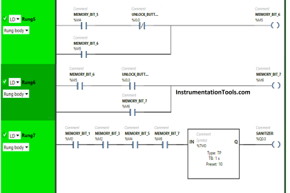
Network 6 – Sequencer
Shift left instruction is used to shift and cycle memory bit “1” through memory M1.0, M1.1, and M1.2.
A positive signal edge pulse at M2.0 activates the shift register by integer 1.
Network 7 – Sampling Point A
Solenoid valve connected at output Q125.1 for sampling point A opens for sampling gas to flow through to the detectors when memory M1.0 is set to “1” state.
The solenoid valve deactivates when M1.0 changes state to “0”.
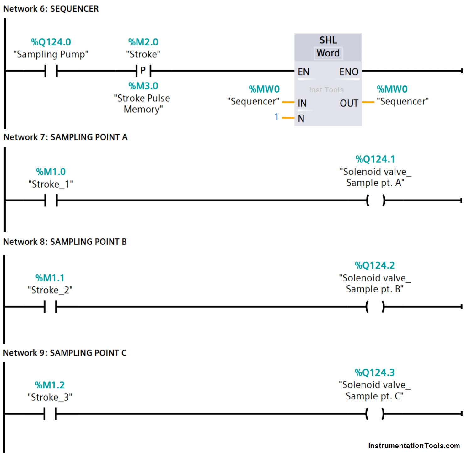
Network 8 – Sampling Point B
Solenoid valve connected at output Q125.2 for sampling point B opens for sampling gas to flow through to the detectors when memory M1.1 is set to “1” state.
The solenoid valve deactivates when M1.1 changes state to “0”.
Network 9 – Sampling Point C
Solenoid valve connected at output Q125.3 for sampling point C opens for sampling gas to flow through to the detectors when memory M1.2 is set to “1” state.
The solenoid valve deactivates when M1.2 changes state to “0”.
Network 10 – Hydrocarbon Sensor Sensor Input Scaling
The hydrocarbon (HC) sensor is connected at the analog input IW752, using a SCALE function to convert the input value (integer) into a floating-point number that is scaled to physical units (%LEL – the percentage of lower explosive limit) between a low limit and high limit of the value range at double word MD10.
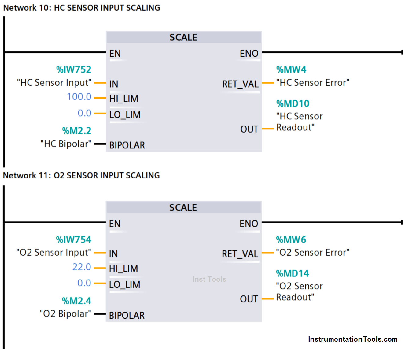
Network 11 – O2 Sensor Input Scaling
The oxygen (O2) sensor is connected at the analog input IW754, using a SCALE function to convert the input value (integer) into a floating-point number that is scaled to physical units (%V – the percentage of volume) between a low limit and high limit of the value range at double word MD14.
Network 12 – H2S Sensor Input Scaling
The hydrogen sulfide (H2S) sensor is connected at the analog input IW756, using a SCALE function to convert the input value (integer) into a floating-point number that is scaled to physical units (PPM – parts per million) between a low limit and high limit of the value range at double word MD18.
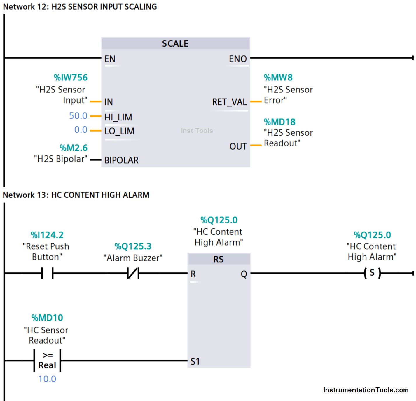
Network 13 – HC Content High Alarm
When the HC content, the converted value of the sampling gas is equal to or greater than 10.0 %LEL but not exceeding the high limit value of 50.0 %LEL.
An HC content high alarm is triggered at output Q125.0. This sets the input S1 of reset/set (RS) flip-flop to signal state “1” irrespective of the signal state at input R.
Network 14 – HC Sensor Fault
When the HC sensor value is greater than the high limit (HI_LIM) or less than the low limit (LO_LIM) as a result of a short circuit, open circuit, or out-of-range sensor, an error signal state “1” is output at MW4 of the scale function and thus sets the RS flip-flop to signal state “1” to activate an HC sensor fault.
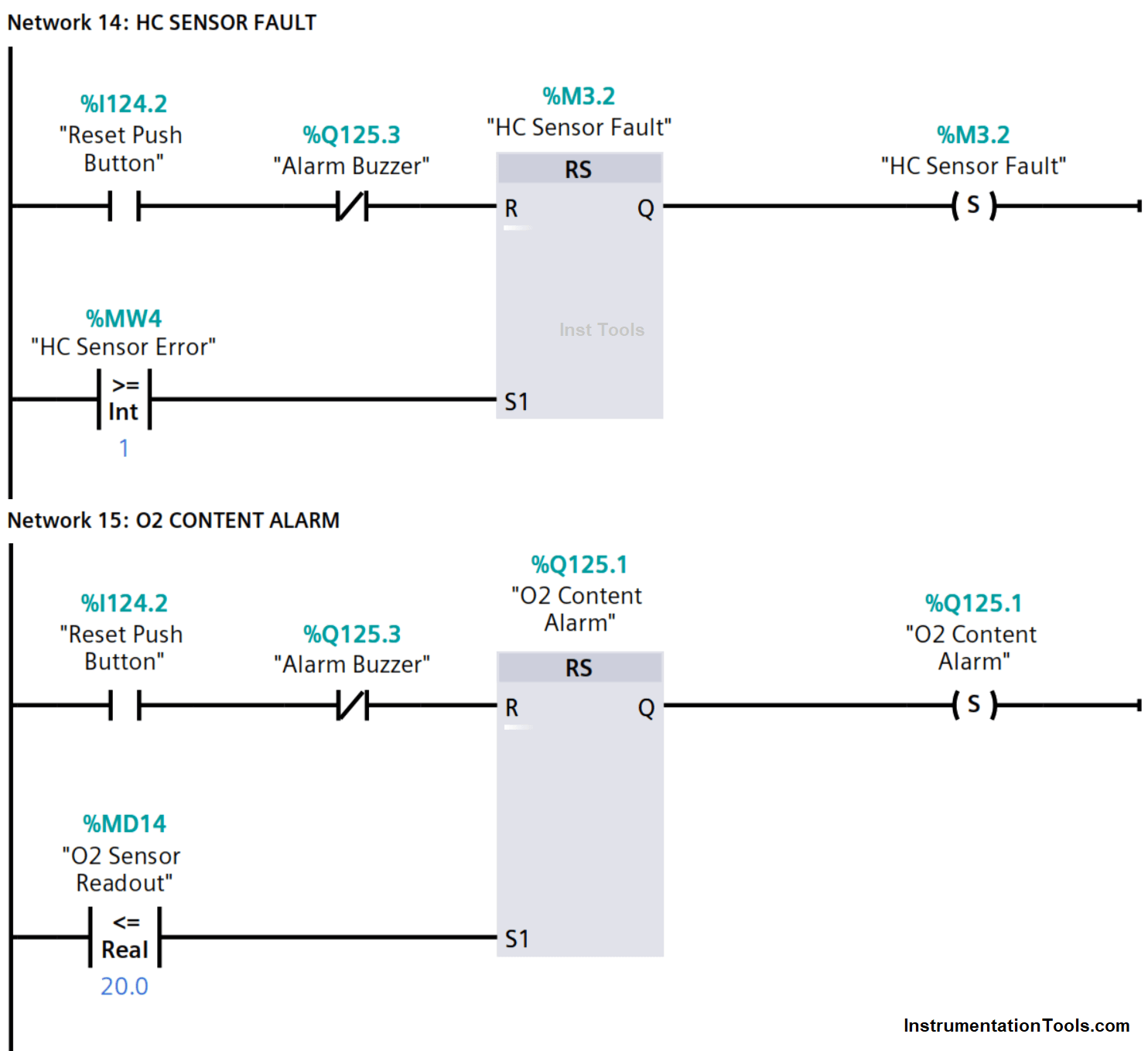
Network 15 – O2 Content Alarm
When the oxygen content, the converted value of the sampling gas is less or equal to 20.0 %V but not less than the low limit value (LO_LIM) of 0.0 %V.
An oxygen content low alarm is triggered at output Q125.1. This sets the input S1 of reset/set (RS) flip-flop to signal state “1” irrespective of the signal state at input R.
Network 16 – Oxygen Sensor Fault
When the oxygen sensor value is greater than the high limit (HI_LIM) or less than the low limit (LO_LIM) as a result of a short circuit, open circuit, or out-of-range sensor, an error signal state “1” is output at MW6 of the scale function and thus sets the RS flip-flop to signal state “1” to activate an oxygen sensor fault.
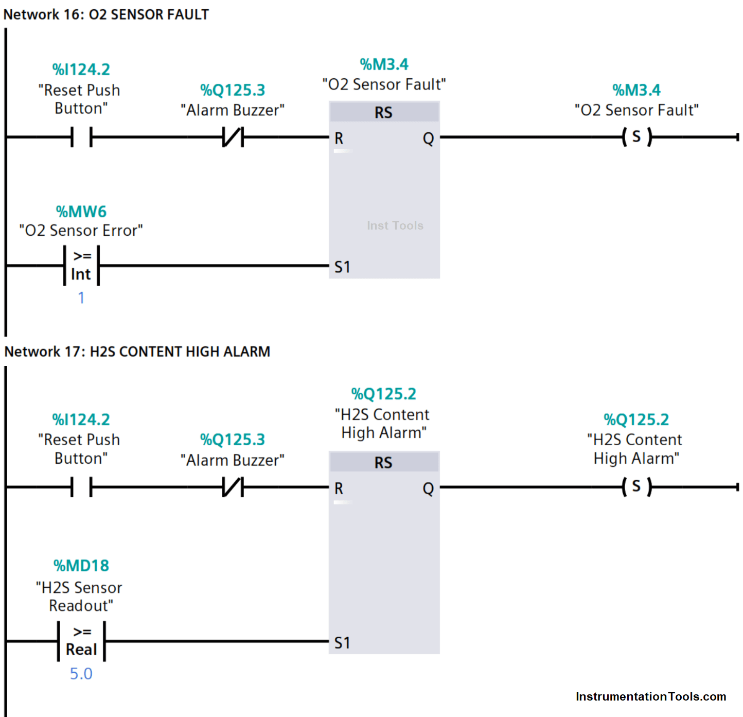
Network 17 – H2S Content High Alarm
When the H2S content, the converted value of the sampling gas is equal to or greater than 5 PPM but not exceeding the high limit value of 50 PPM.
An H2S content high alarm is triggered at output Q125.0. This sets the input S1 of reset/set (RS) flip-flop to signal state “1” irrespective of the signal state at input R.
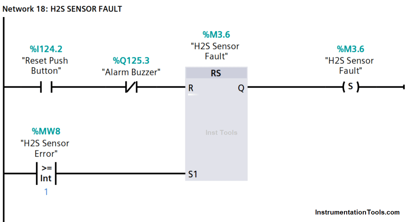
Network 18 – H2S Sensor Fault
When the H2S sensor value is greater than the high limit (HI_LIM) or less than the low limit (LO_LIM) as a result of a short circuit, open circuit, or out-of-range sensor, an error signal state “1” is output at MW8 of the scale function and thus sets the RS flip-flop to signal state “1” to activate an H2S sensor fault.
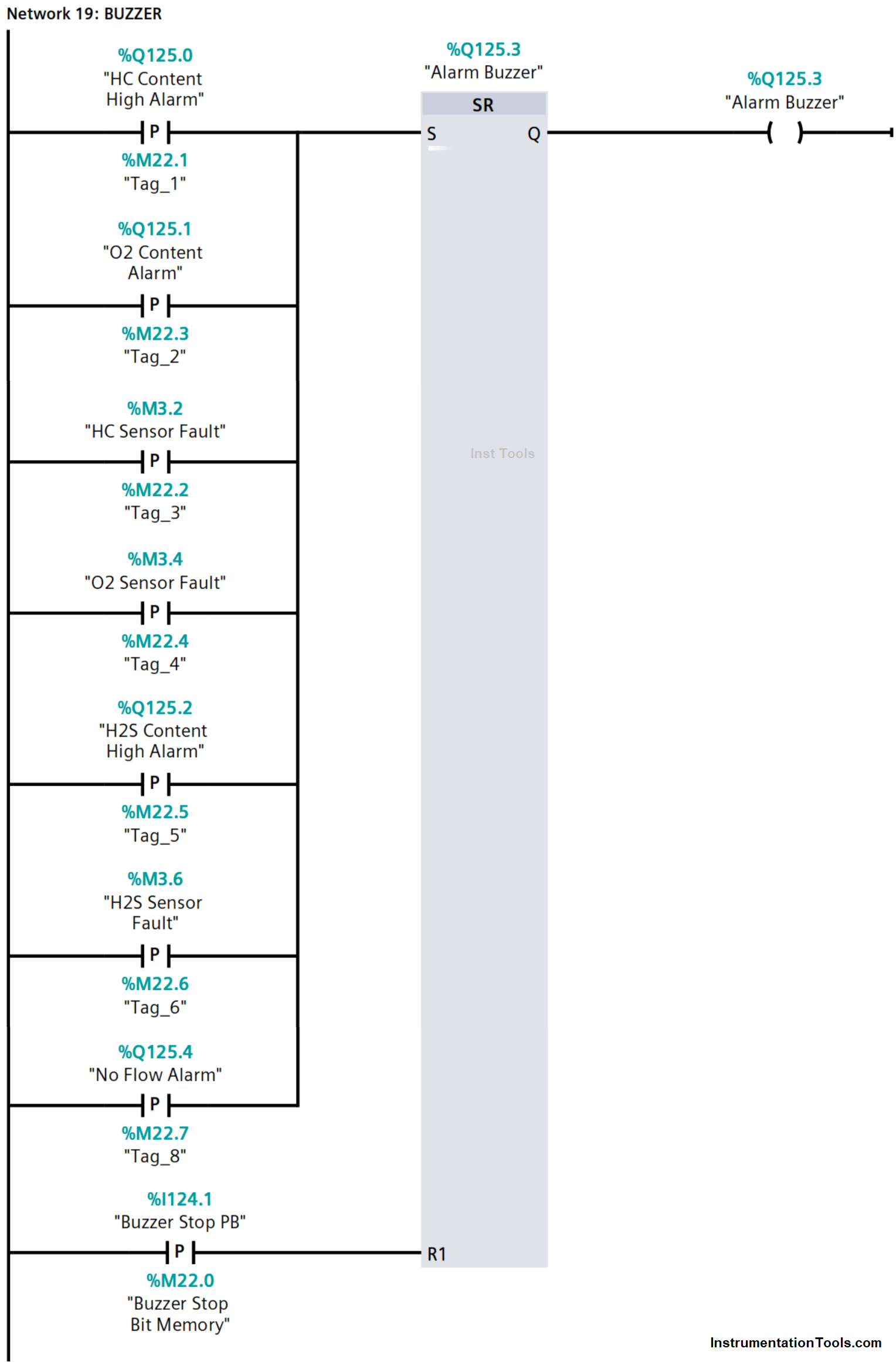
Network 19 – Buzzer
Gas content alarm, sensor fault, or no flow alarm sets the RS flip-flop to signal state “1” hence activating the buzzer at output Q125.3.
A positive signal edge of the buzzer stop PB, I124.1 resets the RS flip-flop to silence the buzzer despite the alarm or fault being active, that is signal state “1” at input S.
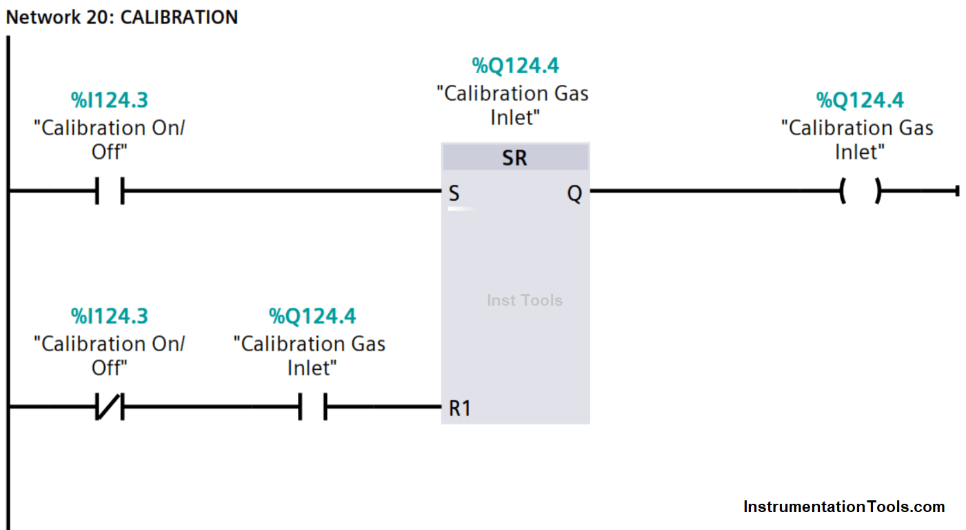
Network 20 – Calibration
The calibration switch, I124.3 when activated, sets the RS flip-flop to signal state “1” thereby energizing the calibration solenoid valve at output Q124.4.
Calibration gas can then be introduced through the calibration port to test and/or calibrate the sensors.
Network 21 – Stop of Sequence
The switching ON of the calibration switch stops the sampling sequence and deactivates all sampling points; Q124.1, Q124.2, and Q124.3.
A zero (“0”) bit is moved to MW0 resulting in de-energizing the sampling point’s solenoid valves.

An alarm or a fault condition is acknowledged by firstly pressing the buzzer stop push button to silence the buzzer, and then pressing the reset push button only after rectifying the alarm or fault.
Author: Kweku Atta Hagan, TMIET