A transformer is a very important component in electrical applications. It is used to step up or step down a voltage. It can come in both lower and higher voltages. For higher voltages (more than 500 kVA), mostly oil-filled transformers are used.
As they work in higher voltages, there are bound to occur many internal faults like insulation failure, oil failure, windings failure, partial discharge, short circuits, arcing, etc.
If these failures are not detected, then they will result in damage to the transformer. For this, a special type of relay called the Buchholz relay is used.
In this post, we will learn the concept of a Buchholz relay.
What is a Buchholz Relay?
The Buchholz relay is used to detect internal faults in an oil-filled transformer. Remember that oil is used as insulation for the transformer body. Buchholz Relay works on the theory of gas detection.
The Buchholz relay is also termed as safety device used in the oil-filled transformers.
Refer to the below image for understanding.
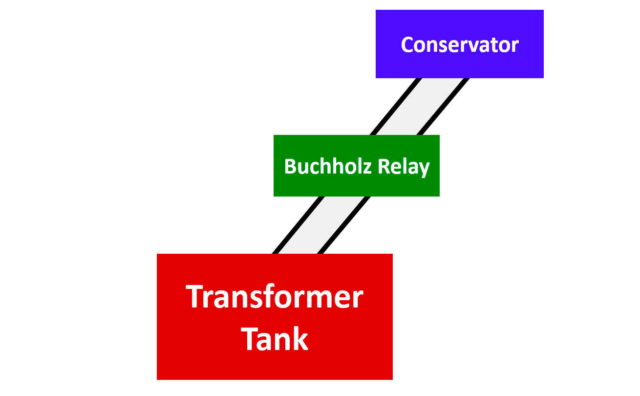
When internal faults occur inside, the current shoots up to a very high abnormal range. This high current automatically increases the operating temperature inside. As oil is filled inside, due to the excess heat generated, it starts to evaporate. As it starts to turn into gaseous form, moves upwards towards the oil conservator.
The relay is placed between the conservator and transformer tank (body). It detects this gas and immediately trips the circuit. This means the transformer is shut off for operation, which prevents any untoward incident.
Working Principle of Buchholz Relay
As discussed earlier, the Buchholz relay works on gas detection. Refer to the below image for understanding. It majorly consists of two float switches (one upper and one lower). It is arranged exactly between the transformer tank output and the conservator input.
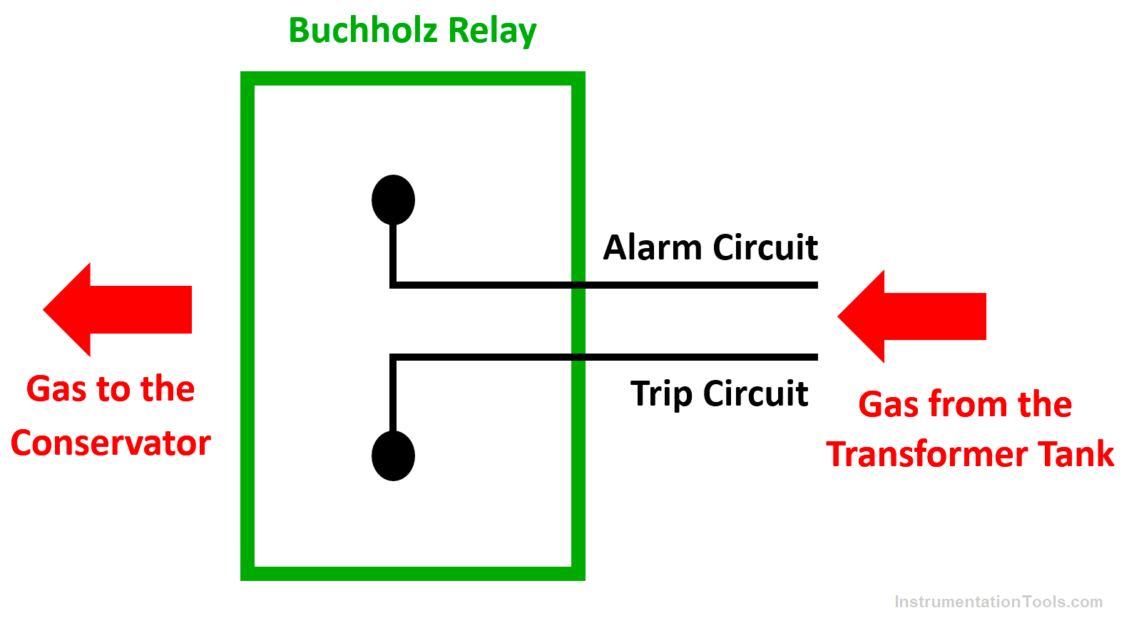
Now, the formula is simple – the less the trip current, the less the heat generated, and the less will be gas generated; the more the trip current, the more will be heat generated and more will be gas generated.
So, in a normal working conditions without any trip, there will no gas from the tank into the transformer. But, in an abnormal condition with any failure, the oil will start to evaporate and gas will be generated. This gas will then start flowing through the relay to the conservator reservoir.
Now, you can see that the gas first enters from the lower entry and goes out from the relay through the upper entry. The lower entry has a lower float (blue color circle) and the upper entry to has an upper float (blue color circle).
The float’s mechanical design is such that the upper float can be displaced by a small amount of gas, while the lower float requires a rapid and substantial gas displacement. In case of minimal gas presence, the upper part will be affected while the lower part will remain unaffected.
After some time, the gas will slowly start moving the upper float, and once moved, it will switch the contact of an alarm circuit to generate an alarm. This will indicate that a failure has started to generate in the transformer tank.
If the gas suddenly moves swiftly and in a large quantity from the bottom entry, then its force will move the lower float. This will immediately switch the contact of the trip circuit and trip the transformer connection. Thus, this relay will prevent the transformer from being damaged.
The mechanical lock is provided in that relay so that one can lock the movement of mercury switches (float) when oil is topping up in the transformer. This mechanical locking also helps to prevent unnecessary movement of breakable glass bulbs of mercury switches during transportation of the Buchholz relays.
Schematic Diagram of a Power Transformer
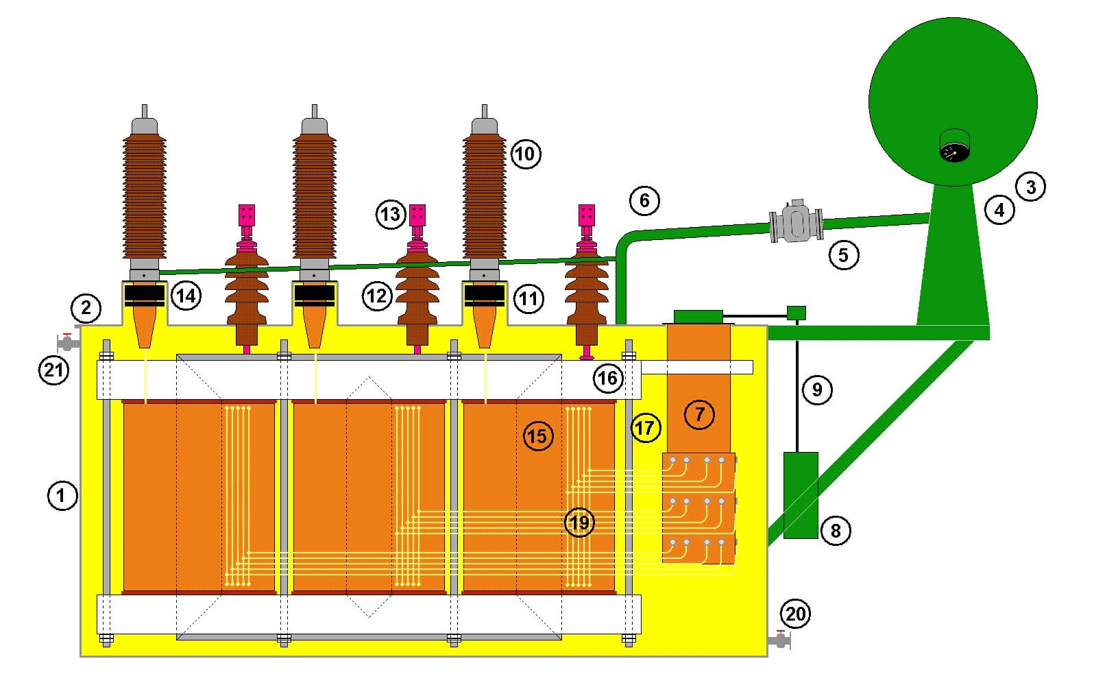
The part numbers are mentioned below.
- Tank
- Lid
- Conservator tank
- The oil level indicator (end of conservator tank)
- Buchholz relay for detecting gas bubbles after an internal fault
- Piping to conservator tank and Buchholz relay
- Tap changer to change output voltage
- The motor drive of the tap changer (can be controlled by an automatic voltage regulator)
- Drive shaft for tap changer
- High voltage (HV) bushing connects the internal HV coil with the external HV grid
- High voltage bushing current transformers for measurement and protection
- Low voltage (LV) bushing connects LV coil to LV grid
- Low voltage current transformers .
- Bushing voltage-transformer for metering the current through the passing bushing
- Core
- Yoke of the core
- Limbs connect the yokes and hold them up
- Coils
- Internal wiring between coils and tapchanger
- Oil release valve
- Vacuum valve
In this way, we saw the working of the Buchholz relay.
If you liked this article, then please subscribe to our YouTube Channel for Electrical, Electronics, Instrumentation, PLC, and SCADA video tutorials.
You can also follow us on Facebook and Twitter to receive daily updates.
Read Next:
- Industrial Circuit Breakers
- Electrical Motor Concepts
- Relays in Air Circuit Breaker
- Induction Motor Over Voltage
- Purpose of Electrical Substation


![Multi-Tank Liquid Level Control System with Fill Priority [PLC]](https://instrumentationtools.com/wp-content/uploads/2025/07/Multi-Tank-Liquid-Level-Control-System-with-Fill-Priority-PLC-330x220.jpg)