Design a ladder logic for PLC level control of two tanks. Learn the PLC programming with practice problems.
PLC Level Control of Two Tanks
Problem Description
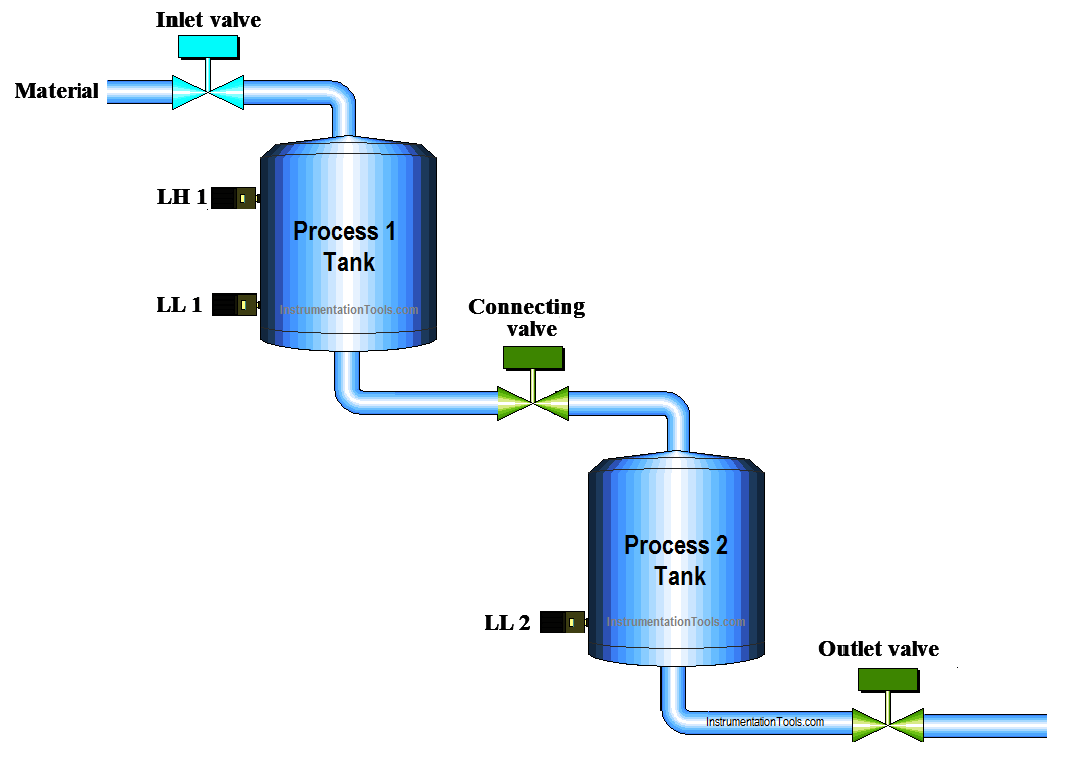
Two simultaneous process are to be performed in two separate tanks which are connected through a valve.
First Process takes place in process tank 1 and second process takes place in tank 2. Write the ladder program for level controlling of two tanks in PLC.
Problem Diagram
Problem Solution
Arrange two pressure controlled tanks for processes. Process 1 will be done in process 1 tank and process 2 will be done in process 2 tank.
Use an inlet vale for material inlet in process 1 tank. Add one more valve between two tanks as a connecting valve.
Consider two sensors (High and Low) for process 1 tank and consider only low sensor for process 2 tank.
For this application we can use PLC, we will write PLC program for this application.
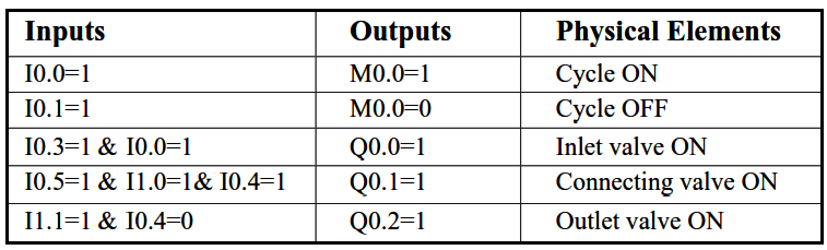
List of inputs and outputs
Digital Inputs
- Cycle START :- I0.0
- Cycle STOP :- I0.1
- Low level process 1 tank (LL1) :- I0.3
- Low level process 2 tank (LL2) :- I0.4
- High level process tank 1 (LH1) :- I0.5
- Process 1 done :- I1.0
- Process 2 done :- I1.1
Digital Outputs
- Inlet valve :- Q0.0
- Connecting valve :- Q0.1
- Outlet Valve :- Q0.2
M memory
- Cycle ON bit :- M0.0
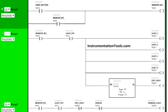
PLC Ladder diagram for level controlling of two tanks
Program Explanation
For this application, we used S7-300 PLC and TIA portal software for programming. We can implement this logic by using other PLC also.
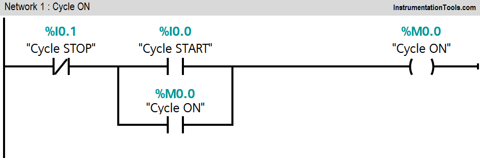
Network 1:
Network 1 is for latching circuit. Whenever START button is pressed (I0.0), Cycle ON (M0.0) bit will be ON. Cycle can be STOP by pressing STOP PB (I0.1).
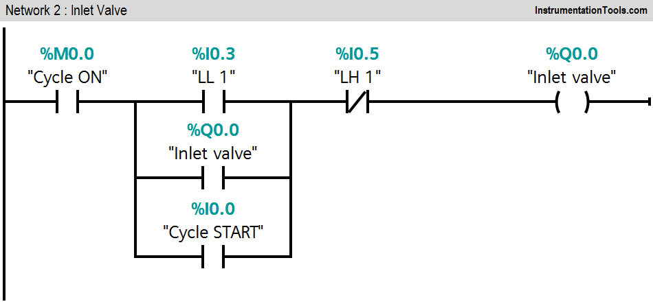
Network 2:
If LL1 (I0.2) is detected and cycle START is pressed, an inlet valve (Q0.0) will be ON. Consider LH 1(I0.3) interlock during this function.
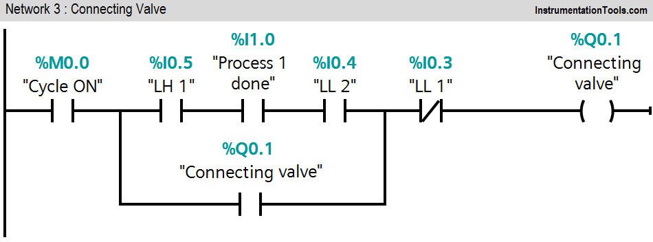
Network 3:
When the level of material of process tank 1 goes high hence LH 1(I0.3) is detected and level of material in process 2 tank goes low, connecting valve (Q0.1) will be ON. This function takes place while PLC is detecting process 1 done command.
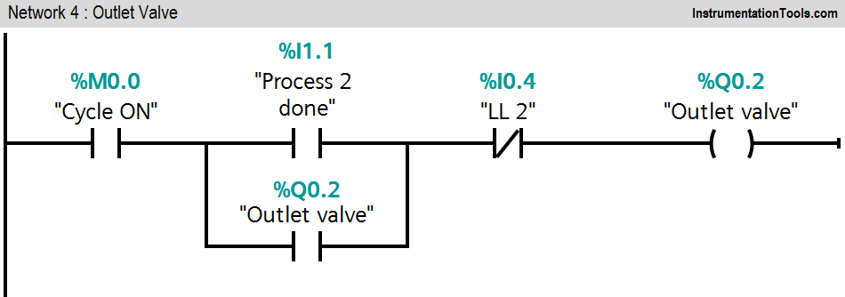
Network 4:
When process 2 is completed and process 2 tank is not low, an outlet valve (Q0.2) will be ON. Cycle ON bit (M0.0) should be ON during the whole cycle.
Note : The above application may be different from actual application. This example is only for explanation purpose only. We can implement this logic in other PLC also.
Result
Author: Bhavesh
If you liked this article, then please subscribe to our YouTube Channel for PLC and SCADA video tutorials.
You can also follow us on Facebook and Twitter to receive daily updates.
Read Next:
- PLC Execution of the Application
- VFD Motor Speed Control
- PLC Heating and Mixing of Products
- Two Way Switch Logic using PLC
- PLC Counting Moving Objects


Where is ladder diagtam for process 1&2. Please mention it, so that new comers can under easily.