Measurements in Water and Steam Circuits
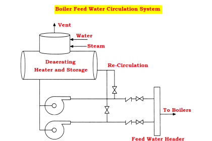
- A stable water circulation system is essential to maintain thermal power plant operation efficiently and uninterruptedly.
- Measurements of the controlled variable and manipulated variable are most important to control all automatic controls like feed water control to boiler drum level control, superheated steam temperature control, steam pressure control, and steam flow control to control the turbine speed are kept in position.
- The following measurements are considered suitable for the above measurement purpose.
- Measurement of feed water flow, make-up water flow, condensate water, feed water, and cooling water.
- Steam flow measurement at various locations.
- Steam pressure measurements at multiple points.
- Measurement of feed water and main steam temperature at various points.
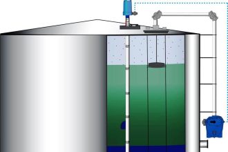
- Deaerator and boiler drum level measurement.
Measurement of Feed Water Flow
- The common method for measuring feed water flow in power plants is by using differential pressure head sensors such as an orifice, rotary displacement meter, V-notch meter, turbine meter, and venturi meter.
- According to the operating principle, the reduction in pressure escorts for the increase of velocity.
- The velocity is increased by inserting a fitting called an orifice or venturi meter to converge to a minimum section and diverge to the normal pipe diameter.
- Proper design of the sensors can define the relation between flow rate Q and the differential pressure D.P developed across the sensor (h)
Q=K√h
Contents
Where
Q = Water flow rate in m³ /hr or T/hr
h = Differential pressure head in mmHg
K= Sensor constant
Installation of Head Flow Meters
- The installation of head flow meters in all power plants is the same for all water flow measurements, such as feed water flow, make-up water flow, condensate water, injection water, etc.
- But, sensor location and flow range vary for particular water flow measurements.
- Primary elements of the head flow meter such as the orifice, venturi meter, Dall tube, or Pitot tube,
- The D.P. transmitter is used to measure the differential head caused by the flowing water at the primary element.
- The D.P. transmitter and the primary element like the orifice require extreme care during installation and connection.
- But it is important to note that the flow meter is required to measure differential pressure.
- If any irrelevant or false head used by the connecting piping causes a serious error.
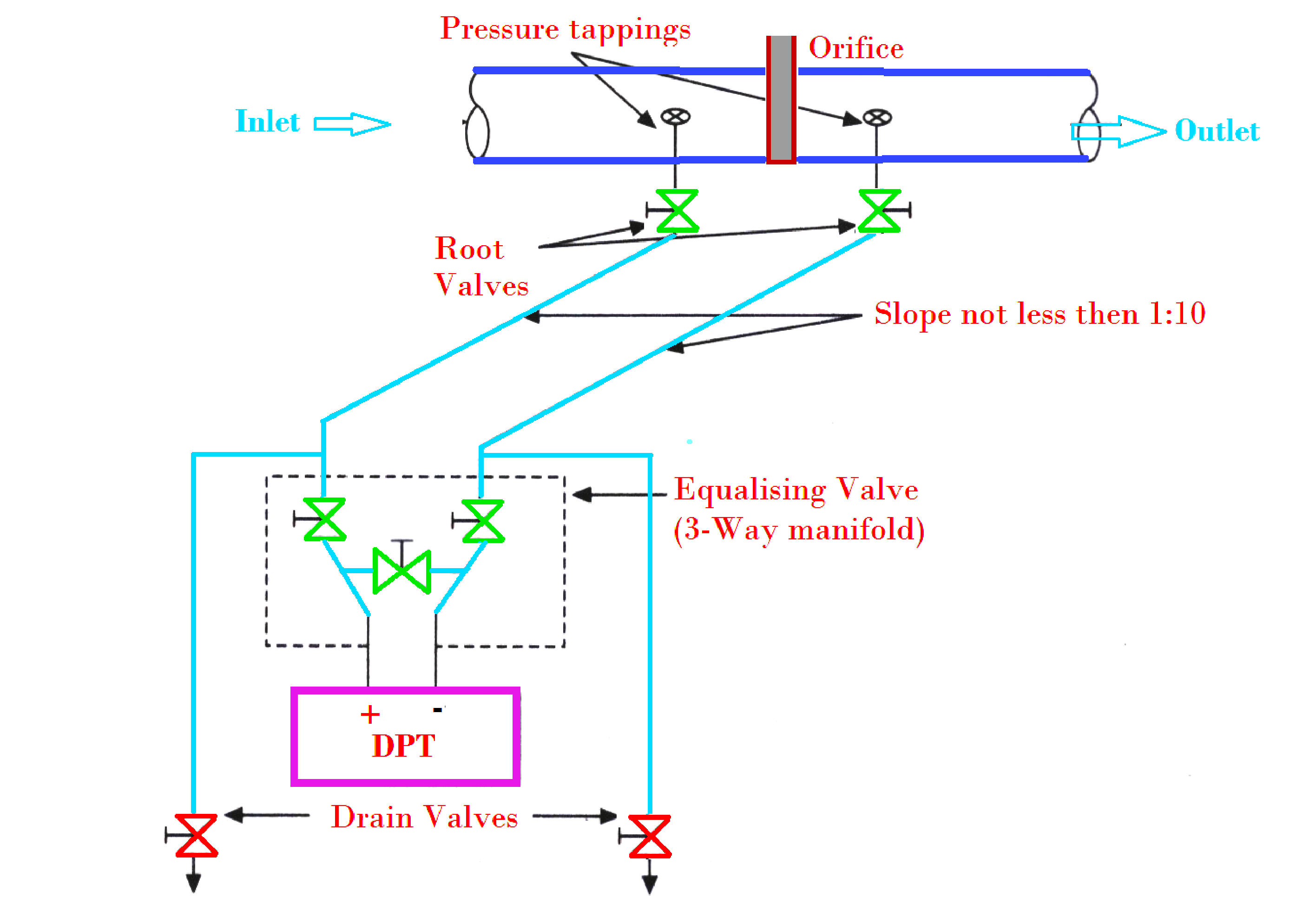
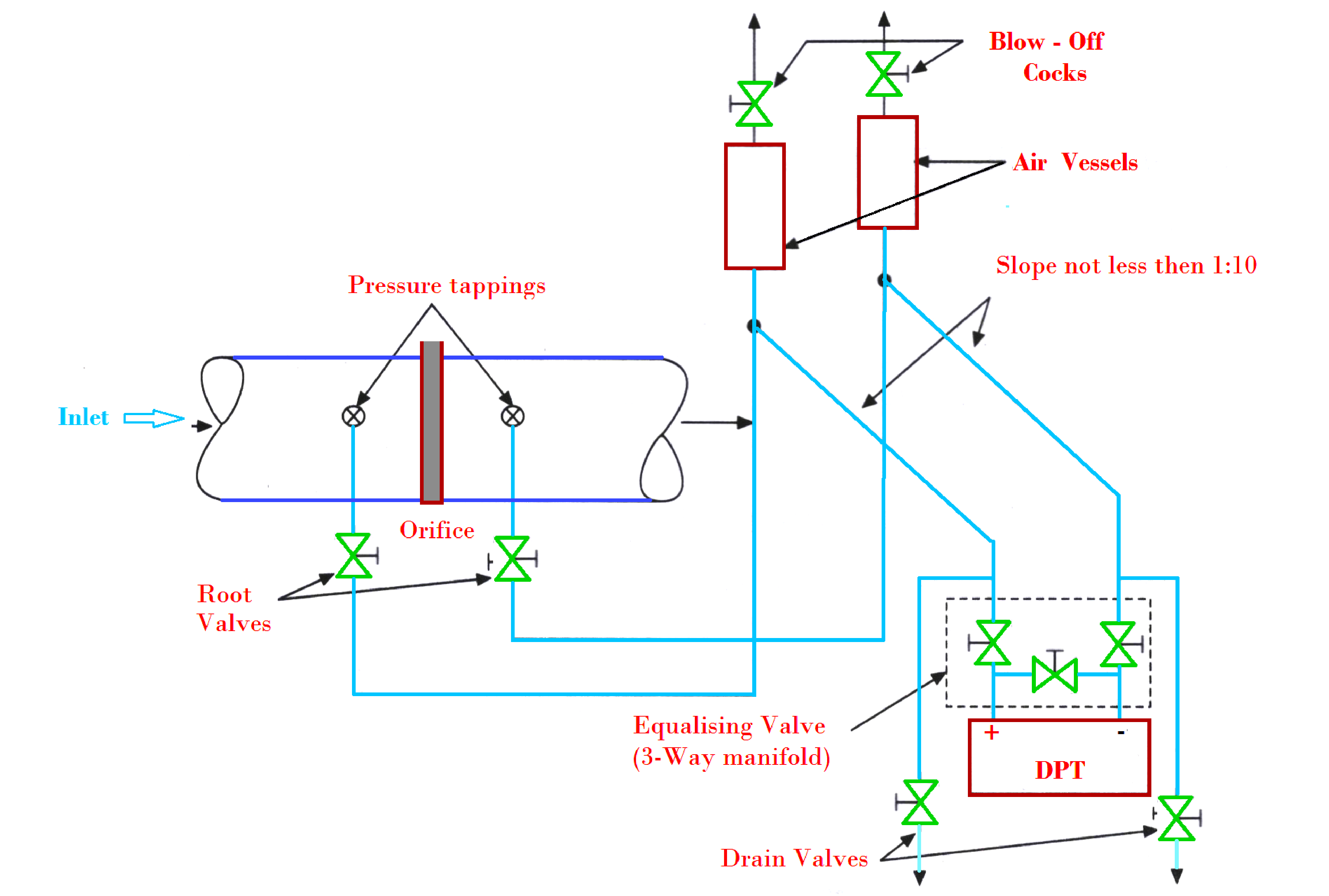
- Pressure piping connects the pipe tapings to DP Transmitters.
- While placing pressure piping care must be taken to avoid false readings in the air or vapor locking.
- If the DP transmitter is installed below the water line, the pressure pipe must be laid at a slope of not less than 1/10.
- If the horizontal distance is too long to allow this slope by direct connection between the orifice and the DP transmitter, then pressure pipes may be taken below or rise above the DP transmitter.
- If the DP transmitter is installed above the water line, the pressure pipe is first placed vertically downwards at a distance of about 0.5 m to reduce the entrance of air or gas, and the pipe is raised continuously at a slope of not less than 1/10 to the transmitter.
- According to the thumb rule, the minimum straight run of about five diameters of the main pipe before and after the restriction called orifice must be provided.
- Elbows, valves, and protection tubes must be avoided in the straight run to permit steady water flow in the vicinity of the orifice.
Differential Pressure Transmitter (DPT)
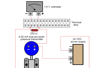
- Differential Pressure Transmitter produces an output signal of 4 to 20mA signal analogous to measured differential pressure.
- Since the flow head equation is nonlinear so it is advisable to make the transmitter current linear to the flow rate.
- For this purpose a square root extractor is utilized, it may be built-in or externally added.
- Generally, Differential Pressure Transmitter requires a DC voltage in the range of 12 V to 42 V.
- These transmitters are called two-wire transmitters because these are connected to various circuits using only two wires.
- Smart transmitters with computer compatibility are used with improved versions of such transmitters.
Steam Flow Measurement
- Steam flow is measured to record the actual quantity of steam generated by individual boilers, the net amount of main steam consumed by steam turbines, and other process requirements.
- In power plants, the steam flow and feed water flow measurements are almost the same.
- In steam flow measurement the pressure piping contains condensate.
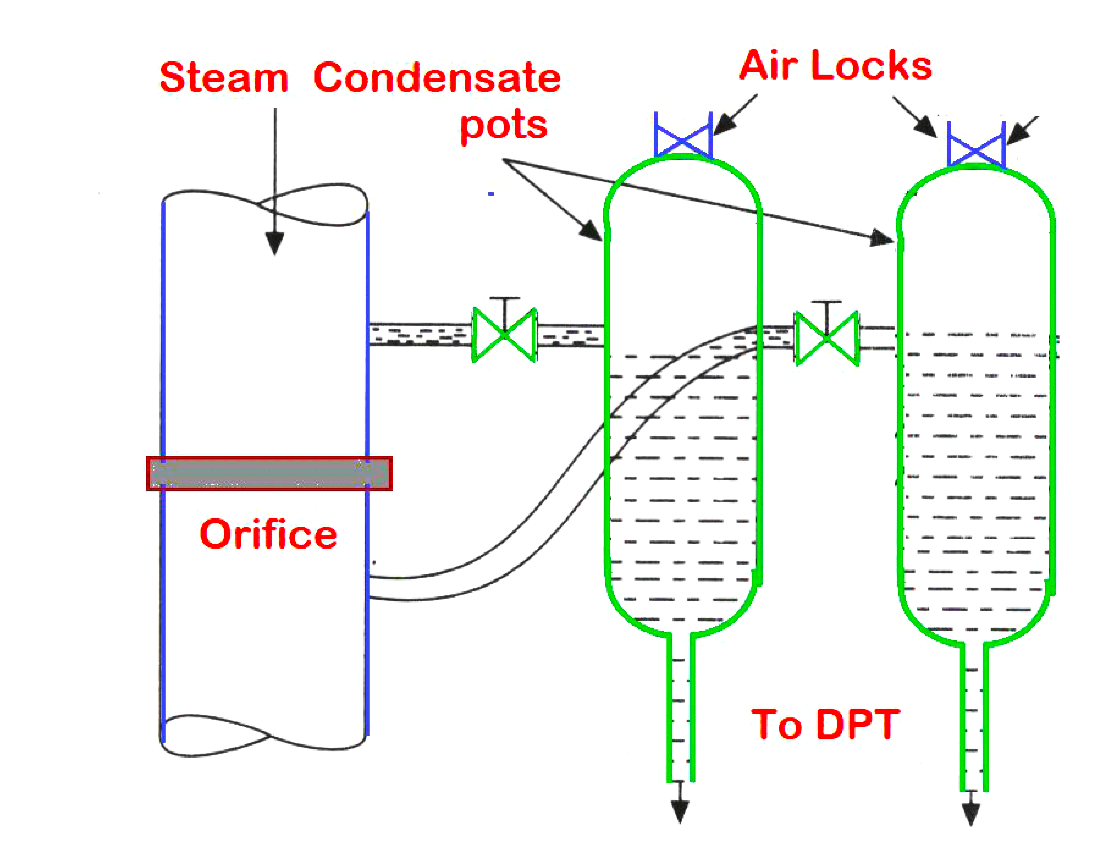
Condensation Pots
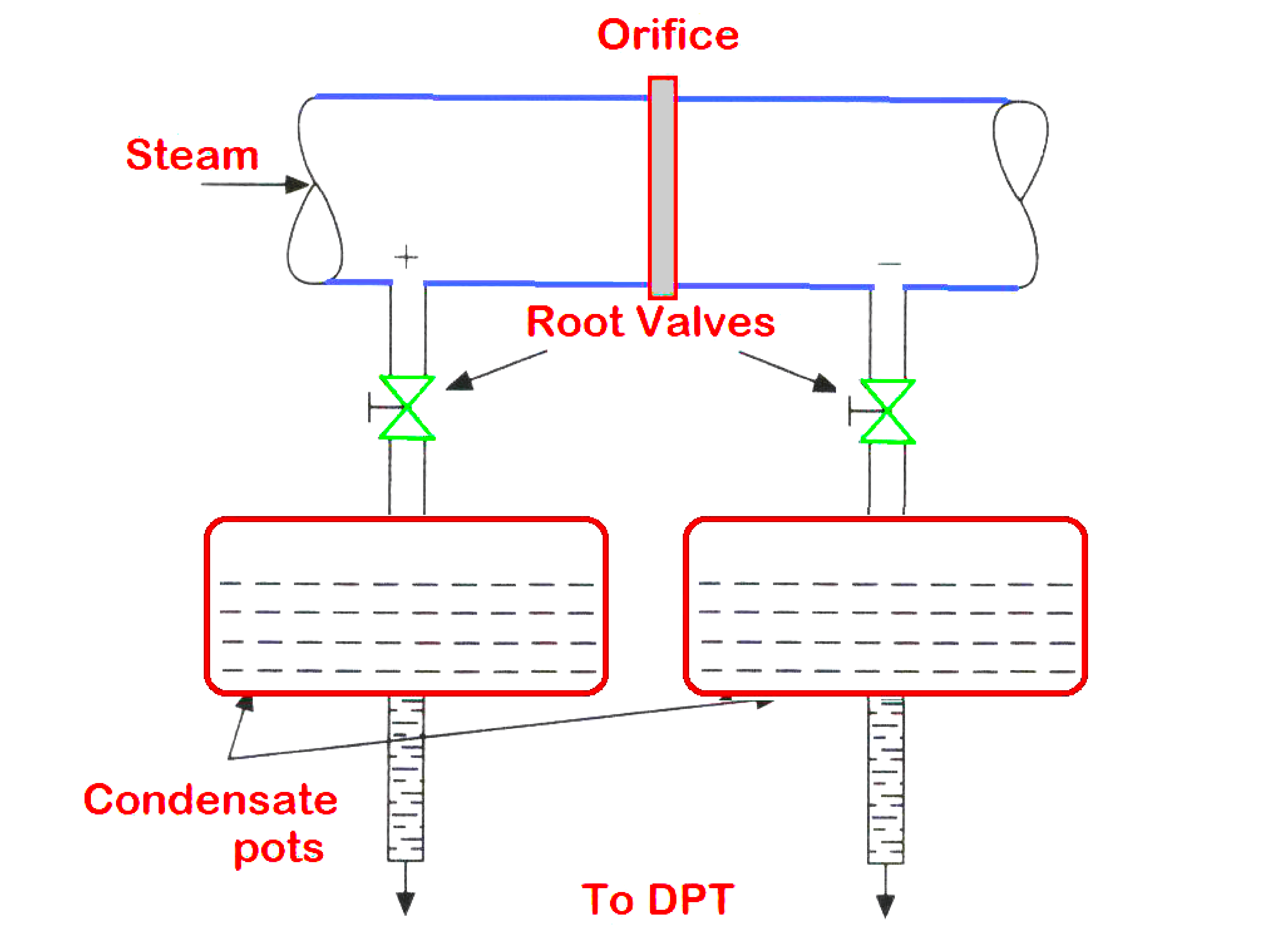
- Condensate pots of adequate size must be connected to pressure tapping to supply enough condensate and to confirm equally high columns above the flow meter. Any excess condensate if present is drained back into the main pipeline.
- The above figure illustrates the typical installation of condensate pots for both horizontal and vertical steam lines.
- Both condensation pots must be placed above the orifice for vertical steam lines.
- The condensation pots are manufactured with different metals such as cast iron, carbon steel, stainless steel, and molybdenum steel are used to match various pressure ranges.
Condensate pots used for various pressure ranges are shown below.
| Metals | Pressure Range |
| cast iron | up to 16 kg/cm² |
| Carbon steel | up to 64 kg/cm2 |
| Stainless steel | up to 100 kg/cm² |
| Molybdenum steel | Above 100 kg/cm² up to 200 kg/cm². |
Temperature and Pressure Corrections
- Steam density is a function of both temperature and pressure.
- Measurement of errors occurs if the density varies significantly with design figures of the restriction such as orifice.
- In such cases, a correction needs to be introduced.
- The correction factor for steam is measured in Tons/hr
- Scaling and biasing are also necessary to obtain a standard electrical signal of 4 to 20 mA analogous to the flow rate.
- For a given differential head range, pressure range and temperature range the input signals are standard 4-20 mA signals.
- The design temperature and pressure are considered constant K factors.
Water and Steam Pressure Measurements
- Measurement of pressure is required at various locations for both water and steam lines.
- Generally, Bourdon tube pressure gauges are used for local indication.
- For cooling water at fewer temperatures, direct piping is used as pressure lines to connect the gauge from the main line.
- For the hot water and main steam line, the Bourdon gauges with siphons called bend tubes are used to avoid direct steam or hot water contact with the bourdon tube.
- An electronic transmitter with standard 4 to 20 mA output is used for transmitting type pressure measurements.
- The sensors used to depend on the range and location
- The sensor may vary from a strain gauge, a capacitive type, a potentiometric type, and an inductive type to a linear variable differential transformer (LVDT) type.
- Piston-type pressure gauges are used to measure very high pressures
- Smart transmitters are widely used to have self-calibration and span adjustment facilities.
- For pressure pipes, valves, and fittings operating pressure and temperature are specified in different standards
- The temperature of water and steam varies from room temperature in the case of cooling water to around 600°C for superheated steam.
- The pressure variations can be expected from about 2 kg/cm² (raw water) to about 100 kg/cm² (boiler feed water).
- Measurement of pressure is carried out to know the pressures of water and steam at various points in the boiler and turbo alternator.
- This is carried out for the purpose of pressure correction in the case of steam flow measurement.
Water Temperature Measurements
- Measurement of the temperature of different waters in the boiler system is most important.
- The different points such as cooling water inlet, condenser outlet, make-up water, condensate water, feed water before and after economizer, feed water before and after Deaerator, and feed water inlet to boiler drum.
- Normally, the temperature of the water is 0 to 100°C, and hence contact type Resistance thermometer detectors (RTDs) act as sensors to detect the temperature.
- Though platinum thermometers are widely used, thermometers composed of nickel and copper are used in only defined regions.
- Pt100 is the commercial name for the platinum thermometer, defining the resistance at 0°C as 100 ohms
- Mercury or Liquid in a glass thermometer is used for onsite indication of process temperature.
Steam Temperature Measurements
- For controlling the boiler operation, it is important to measure the steam temperature at various locations of the boiler such as.
- Steam drum temperature, superheater inlet, and outlet steam temperature, main steam temperature, and turbine inlet temperature.
- The range at different points may vary from about 200°C to about 600°C. Though Resistance Temperature Detectors can be used for low-temperature ranges, and thermocouples are used for high-temperature ranges.
Installation of Temperature Sensors
- As we have seen, the temperature of water and steam varies to a maximum of about 600°C.
- The pressure in those pipes varies from about 2.5 kg/cm² (raw water line) to about 100 kg/cm² in the feed water line.
- Superheated steam temperature and pressure are about 550°C and 60 kg/cm².
- Hence protective shielding is essential for the temperature sensors to operate with such process parameters.
- Appropriate protection tubes and fixing methods are adopted.
- Installing the sensor on the pipeline along with protection tubes
- For low-pressure lines, the sensors are screwed
- For high-pressure lines, direct welding is recommended.
If you liked this article, then please subscribe to our YouTube Channel for Electrical, Electronics, Instrumentation, PLC, and SCADA video tutorials.
You can also follow us on Facebook and Twitter to receive daily updates.
Read Next:
- Turbine Bypass System
- Boiler Light-Up Sequence
- Deaerator Control System
- Turbine Speed Control system
- Boiler Feed Water System