The gas turbine generator is a combination system of a compressor, turbine, and generator. First of all, the air intake is compressed by the compressor. This compressed air will be heated by a fuel combustion process.
This hot and high-pressure air will be expanded in the turbine so that the turbine is rotating and producing a thrust force. This thrust force is used by the compressor itself and also to drive the electrical generator. The electrical generator then producing some electricity or electrical power for further use.
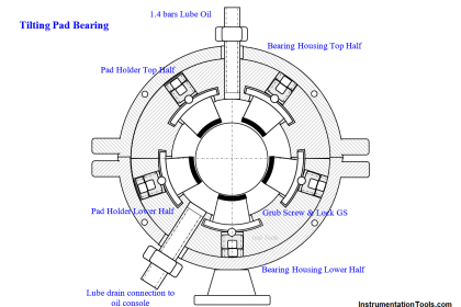
There are three subsystems of the gas turbine generator system, the lube oil system, the fuel gas system, and fire & gas detection & suppression system. The lube oil system’s purpose is to lubricate all the bearing in the turbine.
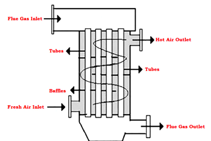
This lube oil system is using a lube oil cooler to dissipate the heat of the lube oil that coming back from the turbine bearing. The temperature and pressure of the lube oil are controlled by the temperature regulator and pressure regulator valve.
The fuel system’s purpose is to regulate the fuel supply so that efficient combustion will be reached in the combustion process. The fuel supply is filtered and controlled before further use in the combustion process.
The fire & gas detection and suppression system are designed to detect any flame or gas accumulation in the turbine skid enclosure. This system will flood the enclosure with CO2 if the fire is developed in the skid enclosure.
Gas Turbine Generator (GTG) Control & Safety System
In general, the gas turbine vendor is supplying a complete package of their gas turbine generator including all field instruments, fire & gas detectors, and a dedicated PLC for the GTG control & safety system.
There are several process variables that need to be monitored and controlled by its dedicated PLC such as turbine temperature, exhaust temperature, lube oil temperature, fuel gas pressure, air intake pressure, fuel gas flow, enclosure flame detection, enclosure gas detection, etc.
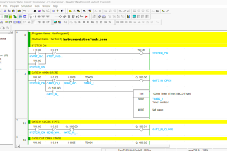
There are also several control functions that need to be done by its dedicated PLC such as start-up and shutdown control etc. See the below picture to get a better understanding regarding the general gas turbine generator control system.
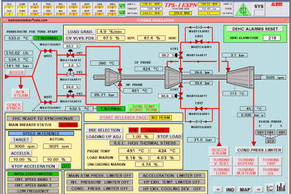
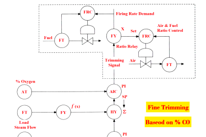
Gas Turbine Control System
Simplified schematic showing advanced PLC-based integrated gas turbine control system for a generator set. The system provides turbine fuel control, temperature control, sequencing/protection, communication interfaces, and more.

Image courtesy: petrotechinc
Share your experience with us on Gas Turbine Control Systems using comments.
Read Next:
- Turbine Protection Devices
- Gas Turbine Questions & Answers
- Troubleshooting of Gas Turbine
- Burner Management System Logics
- Turbine Supervisory Instrumentation