The Turbine Control System is broadly classified into two systems namely,
- Safety Control System
- Process Control System
The purpose of the Safety Control System is to take care of the safety of workers and machinery equipment.
This Safety Control System is intended to eliminate or minimize the activities that cause serious damage to the equipment and to persons working in the power plant. Whereas Process Control System monitors the process operations as per the application requirement.
Safety Control System
- In the turbine safety control system, the shutoff valve works as the master safety element.
- This shutoff valve is operated by a solenoid for quick operation.
- Safety Interlocks provided for safety issues must satisfy safe operating conditions during turbine start-up.
- The shutoff valve is now opened and steam is allowed to pass through the governor to the turbine in the proper way.
- The shutoff valve may get closed for the emergency condition that appears during normal turbine operation.
- High bearing temperatures, lube oil failure, over speed, high vibration, and high displacement are the causes of the shutoff valve needing to be closed.
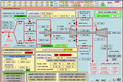
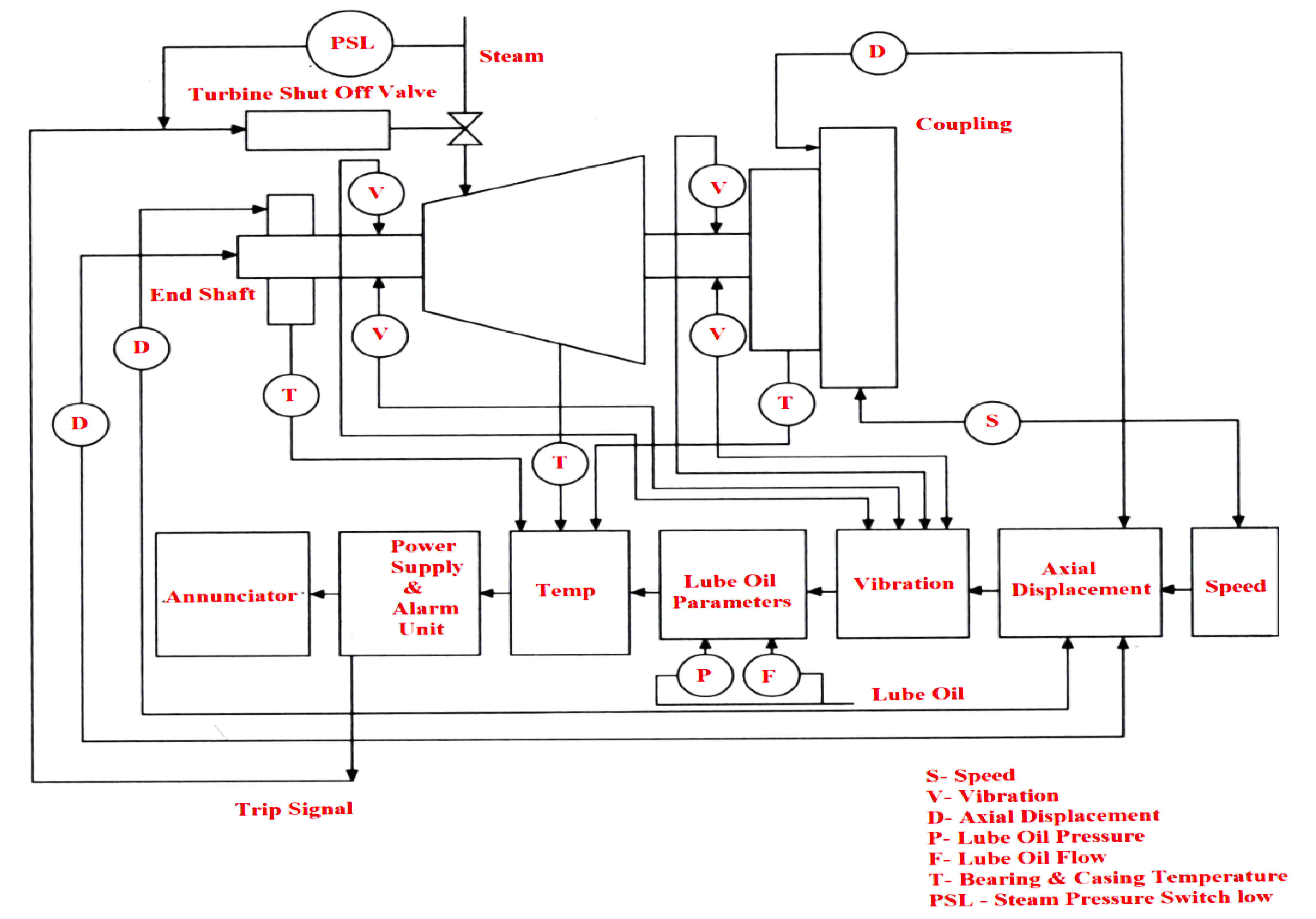
- The figure above shows the overall safety monitoring system of a steam turbine.
- The turbine safety control system includes various measurements.
Pedestal Vibration
- Vibration transducers provide the signals for routine monitoring in the control room by giving indications and warnings to ensure that the plant is not operating in severe conditions that may cause damage.
- Usually for normal operation, some facilities are available for analysis of the vibration signal to provide information with respect to plant operating conditions.
- Turbine pedestal vibration is characterized by quantities, amplitude, frequency, and phase.
Vibration Displacement
- Displacement is the total distance the vibrating part that moves in a given direction.
- It is measured in length. In units of micrometers.
Velocity of Vibration
- The velocity of vibration is defined as the speed at which the part is moving at any instant during the vibration cycle.
- The velocity of vibration during one complete sinusoidal cycle differs from zero to maximum or peak value.
- The value normally adopted for turbine pedestal vibration measurement is the RMS velocity, the units being mm/s.
Acceleration Due to Vibration
- Acceleration is defined as the rate of change of vibration velocity at any instant during the vibration cycle.
- The RMS value in mm/s² is normally displayed by vibration measuring instruments.
Shaft Vibration
- The dynamic movement of the shaft towards the eccentricity locus is known as shaft vibration.
- Steam turbines have several modes of vibration in their operating speed and it shows their responses to imbalance, thermal bends, rubs, and unloading of bearings are clearly observed by measuring the movement of the shaft within the bearings rather than pedestal vibration.
- Shaft vibration measurements are used for monitoring the routine operation of the plant and monitoring radial clearances.
Eccentricity
- Eccentricity is defined as the out-of-center excursion of the axis of rotation of the shaft.
- Generally, it is measured as the diameter of the locus traced out by the shaft center.
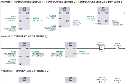
Temperature Measurements
Supervisory temperature measurements include various measurements such as casing temperatures and steam-to-metal temperature differences and thermal gradients.
Metal Temperatures
- Metal temperatures at the HP and IP cylinders are measured by using thermocouples (duplex K type) inserted in holes drilled into the steam chest or cylinder walls.
- Normally these measurements are taken from the inner or the mid-wall position.
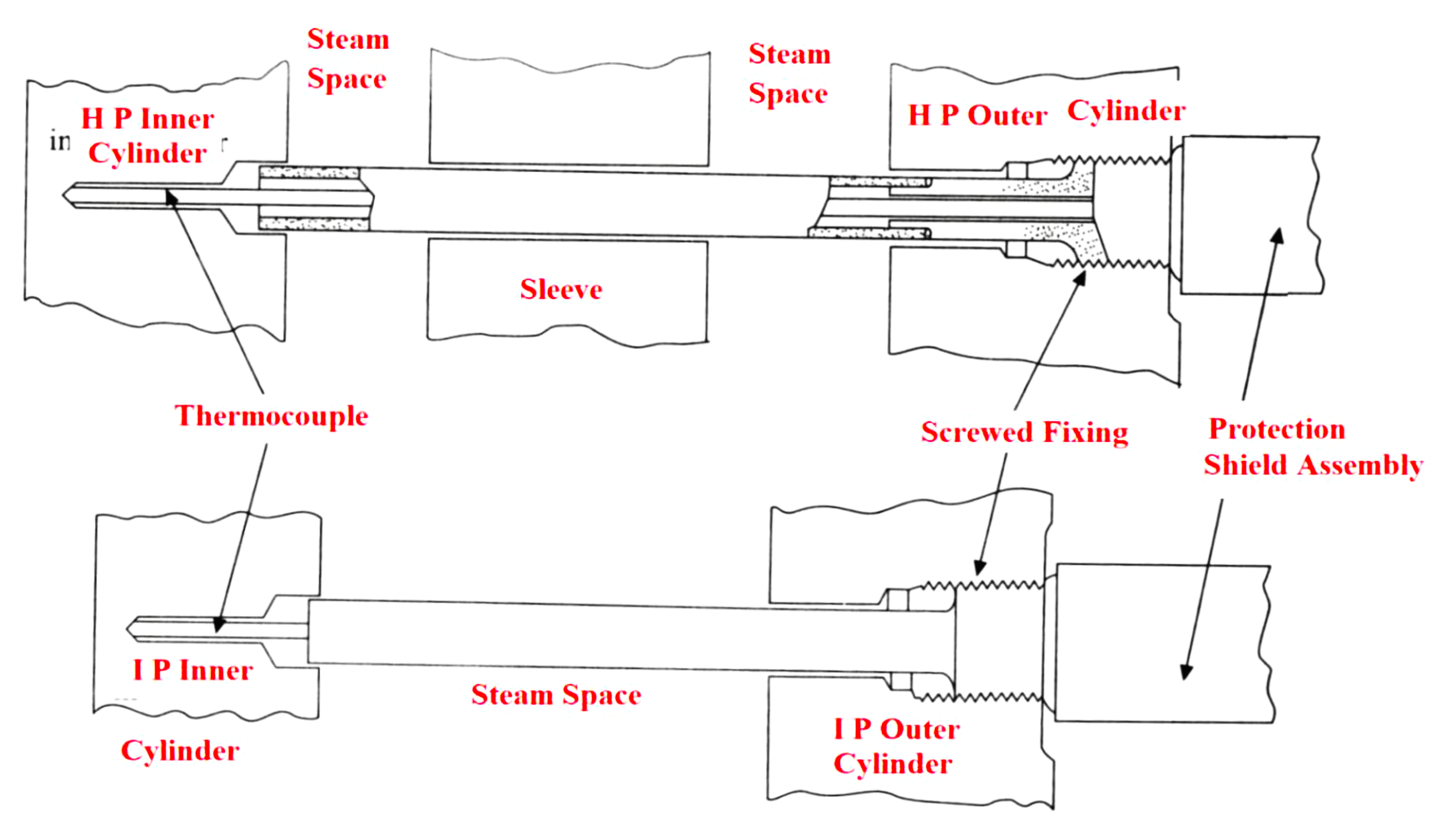
Cylinder Metal Temperatures
- Measurement of metal temperature with a high degree of Reliability at HP and IP cylinder is very important during turbine running and loading.
- Four duplex type-K thermocouples are provided for each measurement, two are fixed at the probe Tip, and two are located at the inner cylinder mid-wall position.
Process Control Systems
- In a power station, the steam turbine must be operated as per application requirements.
- The turbine must respond to the electrical load fluctuations.
- An increase in the electrical load of the alternator makes the coupled turbine decelerate.
- At this time, the process control system allows more steam to compensate and allows the turbine to run at the required speed.
- The decrease in load will have the reverse action.
Application-oriented controls in a Steam Turbine
- Simple Condensing Turbine Application.
- Non-Condensing Turbine Application.
- Extraction Turbine in Pressure Let Down Application.
- Pressure Regulating Extraction Turbine Application
Simple Condensing Turbine Application
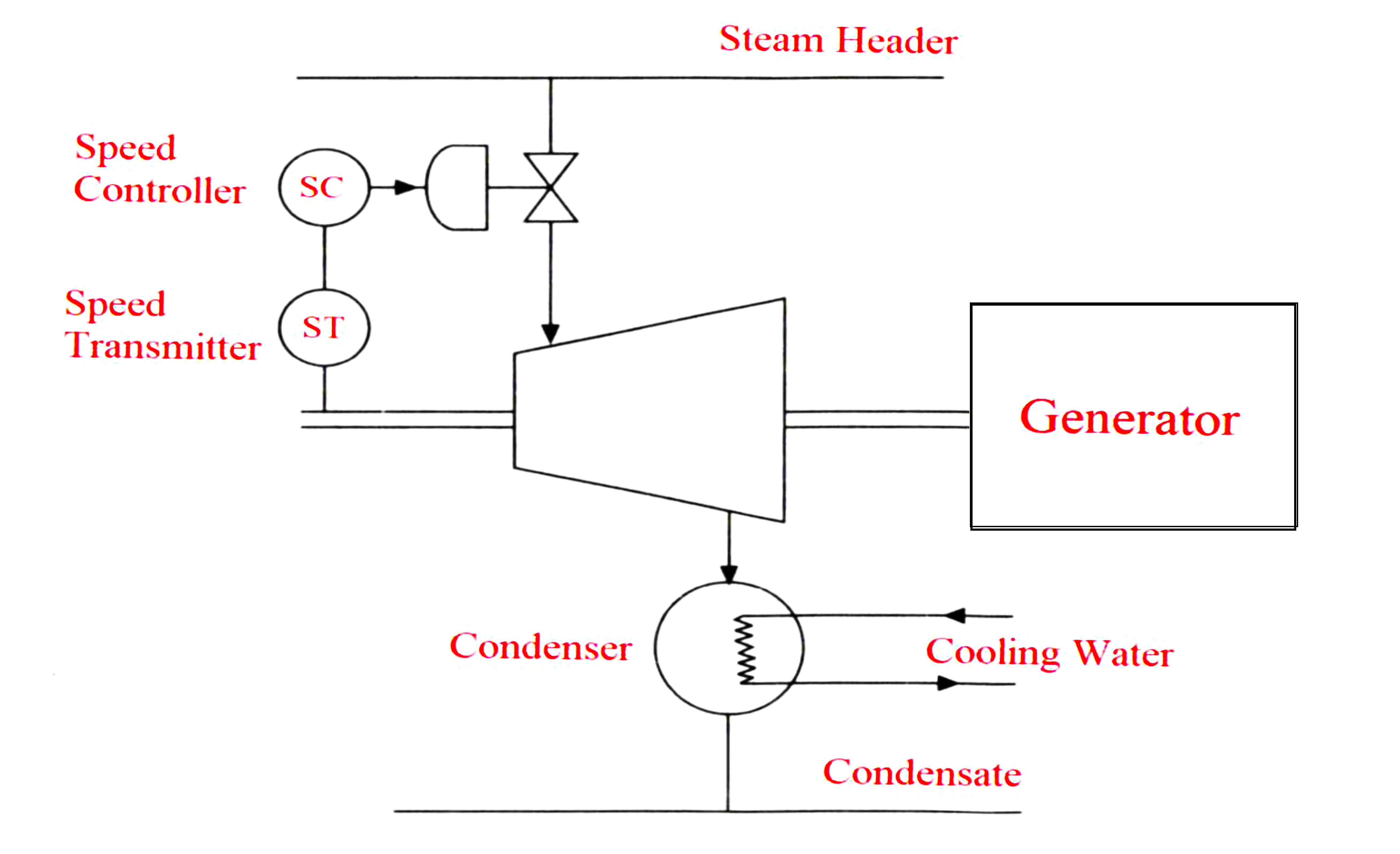
- In power plant applications, the steam turbine acts as a prime mover for some mechanical loads and for the electrical generators to run at a constant speed.
- The energy required is distributed from a steam header, the steam is expanded in a steam turbine, and condensed in the condenser.
- The speed is controlled by a turbine governor.
- In an electronic governing system, the speed is measured by a tachometer and is compared with the set point by the controller.
- The controller output actuates a steam valve to manipulate the steam quantity to match the speed with the set point.
- If the speed is varied due to changes in electrical load, or variations in header pressure, the controller has to respond, correct it and bring the speed back to the set point.
Non-Condensing Turbine Application
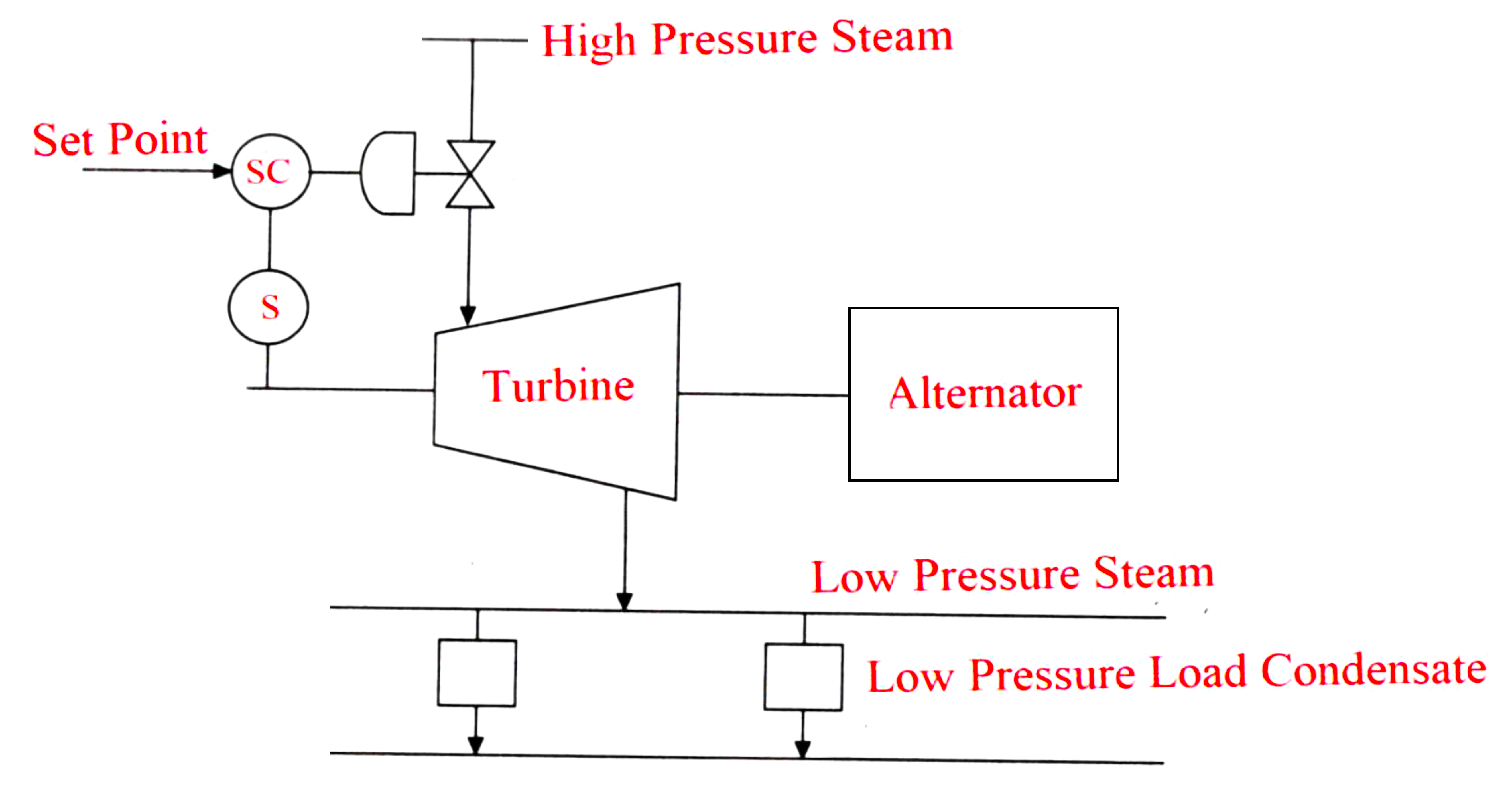
- Power plants have the requirement of low-pressure steam for heating applications such as deaerators.
- In such cases, a non-condensing turbine application may work out to be more economical than condensing one.
- Instead of wasting energy by condensing the extracted steam with higher enthalpy can be beneficially used for low-pressure applications.
Extraction Turbine in Pressure Letdown Application
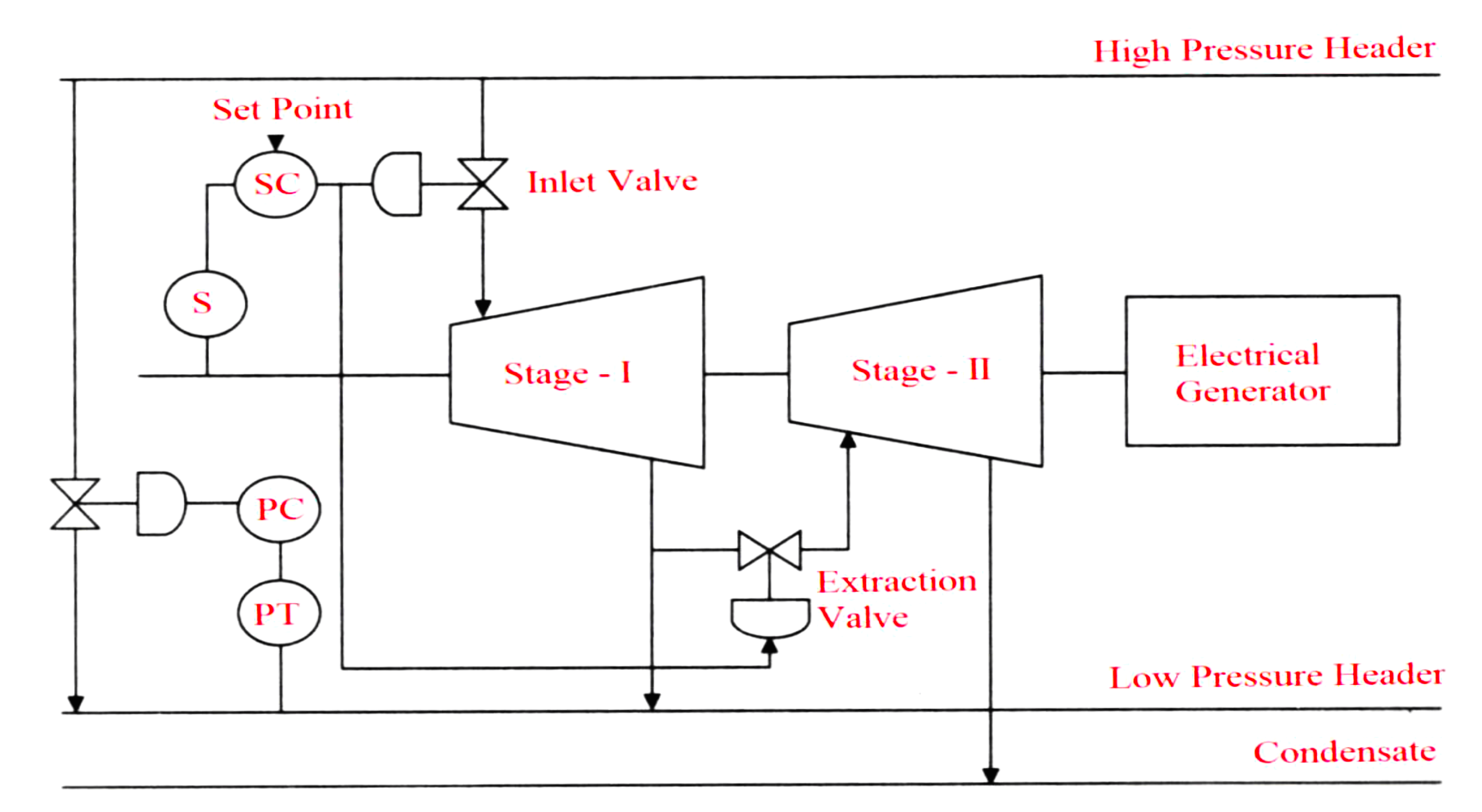
- Extraction turbine in pressure let down application is considered, If there is a higher demand for low-pressure steam than the extraction steam.
- Generally, a steam turbine works in two stages.
- In the first stage, the steam is extracted for low-pressure applications.
- In the second stage, the extracted steam is now shared between the turbine and the low-pressure header.
- If the whole extracted steam or the major portion of the steam is supplied to the second stage, then the low-pressure steam header will not get sufficient steam. In such cases, extra steam from the high-pressure header is supplied directly to the low-pressure header through a Pressure Control Valve.
- The speed Control Valve delivers steam to the turbine and the extraction steam is supplied to the low-pressure header.
- The extraction valve used as an inlet to the second stage remains closed.
- The extraction valve opens to make up the energy if the electrical load demand doesn’t meet his condition.
- Then the low-pressure header may suffer from more steam requirement supplied by the Pressure Control Valve connected between high-pressure headers and low-pressure headers.
Pressure Regulating Extraction Turbine Application
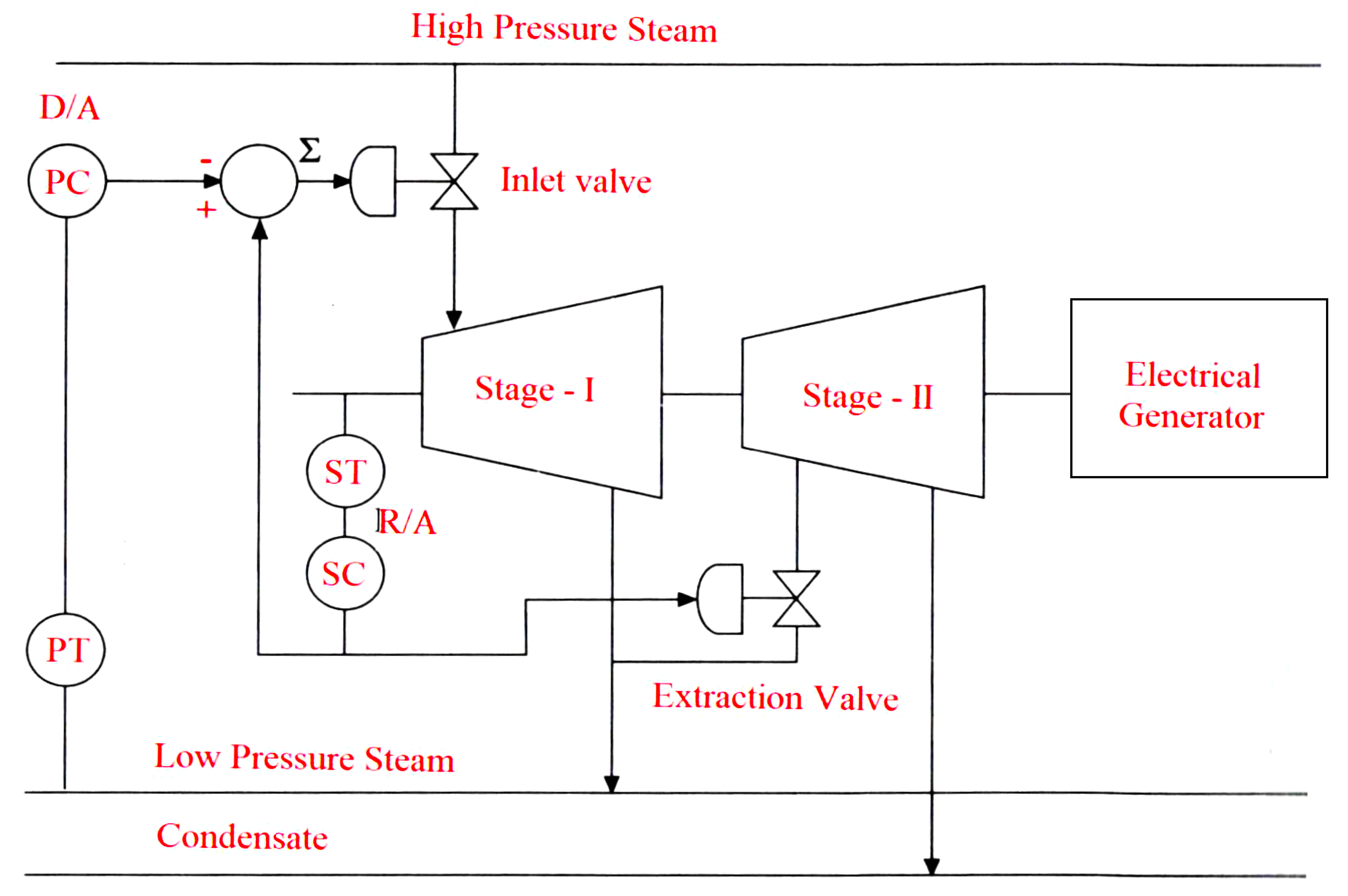
- Pressure-regulating extraction steam turbine application is used if there is low-pressure steam demand that is less than extracted steam.
- The excess steam required to meet the electrical demand or maintain a low-pressure header this pressure may be vented out to the atmosphere.
- The steam inlet to the turbine can be reduced whenever the low-pressure header doesn’t require steam.
- The extra energy required for the shaft is provided by opening the extraction valve to allow more steam into the second stage.
- The speed controller controls both the extraction valve and the inlet valve in a split mode.
- A summing relay is added with positive input from the speed controller and negative input from the pressure controller.
- Whenever there is an increase in pressure in the low-pressure header, the negative input increases making the inlet valve close.
- This makes the turbine slow down requesting the inlet valve to open, but will be again resisted by the pressure controller.
- The reverse-acting speed controller output opens the extraction valve to raise the speed and equilibrium will be achieved after some interaction.
If you liked this article, then please subscribe to our YouTube Channel for Electrical, Electronics, Instrumentation, PLC, and SCADA video tutorials.
You can also follow us on Facebook and Twitter to receive daily updates.
Read Next:
- Turbine Bypass System
- Boiler Light-Up Sequence
- Deaerator Control System
- Turbine Speed Control system
- Boiler Feed Water System