Inst ToolsInst ToolsInst Tools
  • Courses
  • Automation
    • PLC
    • Control System
    • Safety System
    • Communication
    • Fire & Gas System
  • Instrumentation
    • Design
    • Pressure
    • Temperature
    • Flow
    • Level
    • Vibration
    • Analyzer
    • Control Valve
    • Switch
    • Calibration
    • Erection & Commissioning
  • Interview
    • Instrumentation
    • Electrical
    • Electronics
    • Practical
  • Q&A
    • Instrumentation
    • Control System
    • Electrical
    • Electronics
    • Analog Electronics
    • Digital Electronics
    • Power Electronics
    • Microprocessor
  • Request
Search
  • Books
  • Software
  • Projects
  • Process
  • Tools
  • Basics
  • Formula
  • Power Plant
  • Root Cause Analysis
  • Electrical Basics
  • Animation
  • Standards
  • 4-20 mA Course
  • Siemens PLC Course
Reading: Calculate Incident Power in Radar Level Measurement
Share
Font ResizerAa
Inst ToolsInst Tools
Font ResizerAa
  • Courses
  • Design
  • PLC
  • Interview
  • Control System
Search
  • Courses
  • Automation
    • PLC
    • Control System
    • Safety System
    • Communication
    • Fire & Gas System
  • Instrumentation
    • Design
    • Pressure
    • Temperature
    • Flow
    • Level
    • Vibration
    • Analyzer
    • Control Valve
    • Switch
    • Calibration
    • Erection & Commissioning
  • Interview
    • Instrumentation
    • Electrical
    • Electronics
    • Practical
  • Q&A
    • Instrumentation
    • Control System
    • Electrical
    • Electronics
    • Analog Electronics
    • Digital Electronics
    • Power Electronics
    • Microprocessor
  • Request
Follow US
All rights reserved. Reproduction in whole or in part without written permission is prohibited.
Inst Tools > Blog > Practical Questions > Calculate Incident Power in Radar Level Measurement

Calculate Incident Power in Radar Level Measurement

Calculate the percentage of incident power reflected back to the transmitter through the liquid in this radar level measurement application.

Last updated: January 7, 2021 11:00 am
Editorial Staff
Practical Questions
No Comments
Share
2 Min Read
SHARE

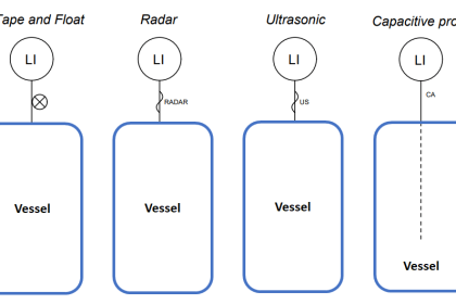
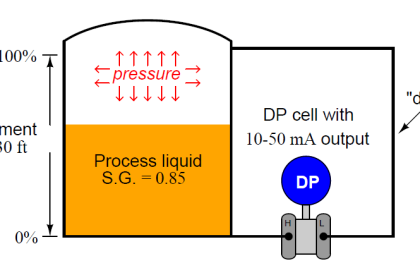
Calculate the percentage of incident power reflected back to the transmitter, and the percentage of incident power transmitted (forward) through the liquid in this radar level measurement application:

Radar Level

Calculate Incident Power in Radar Level Measurement

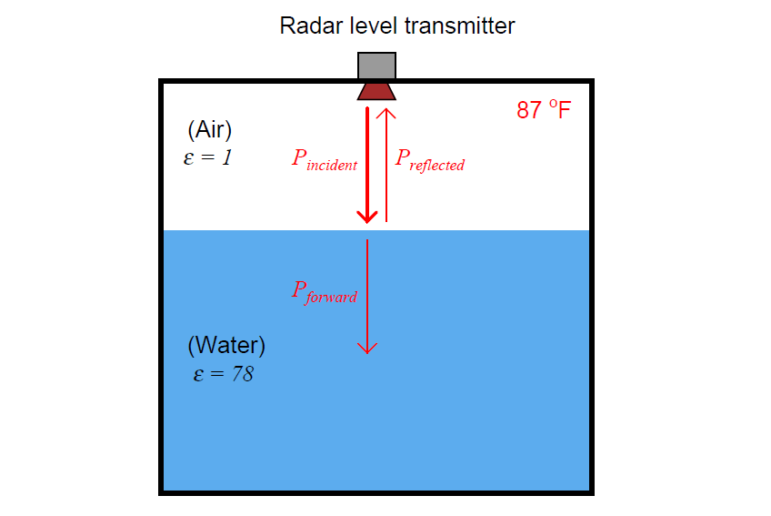
Also, calculate the ullage for this vessel in both units of meters and units of feet/inches, given a reflected pulse (“echo”) time of 11.176 nanoseconds.

Note: the propagation velocity of radio waves in air is approximately 3 × 10⁸ meters per second, the same as the speed of light in a vacuum.

Partial Answer:

Preflected = 63.45%

Ullage = 1.676 meters

More Questions

1. An effective problem-solving technique to apply to the calculation of ullage is to simplify the problem and solve that simplified problem.

In this case, an easy way to “simplify the problem” is to change the numerical values for echo time and speed of light until the solution for ullage becomes obvious even without using a calculator.

Then the formula we must use to calculate any time/speed/ullage echo problem will be apparent. Apply the “simplify the problem” technique to this ullage calculation.

2. Would you say this is an example of good signal reflection, or poor signal reflection? In general terms, what condition(s) make for strong reflected signals for a radar-based level instrument?

Share your answers and explanation with us through the below comments section.

Read Next:

  • Ultrasonic Level Measurement
  • Purpose of Tank Gauging Level Measurement
  • Guided Wave Radar Questions and Answers
  • Stilling Well in Interface Level
  • Level Instruments Specifications

Credits: Tony R. Kuphaldt

Don't Miss Our Updates
Be the first to get exclusive content straight to your email.
We promise not to spam you. You can unsubscribe at any time.
Invalid email address
You've successfully subscribed !

Continue Reading

Pneumatic Moment-balance Differential Pressure Transmitter
Displacer Level Transmitter Questions
What is the Purpose of Chemical Seals Pressure Transmitter?
Programmable Logic Controller (PLC) Questions and Answers – 3
Resistance Temperature Detector (RTD) Questions – 1
Draw the Symbols for Liquid Level Measuring Instruments
Share This Article
Facebook Whatsapp Whatsapp LinkedIn Copy Link
Share
Leave a Comment

Leave a Reply Cancel reply

Your email address will not be published. Required fields are marked *

Stay Connected

128.3kFollowersLike
69.1kFollowersFollow
210kSubscribersSubscribe
38kFollowersFollow

Categories

Explore More

How a Bourdon Tube Pressure Gauge might be Adjusted for Linearity?
Identify the Pressure Gauge Error
Practical Process Control System Questions & Answers – 7
Displacer Level Transmitter Question & Answer
Calculate the Magnitude of Hydrostatic Pressure
Double Block and Bleed Valves Opening or Closing Sequence
Pressure Transmitter Re-Range Questions
Process Control High Level Alarm Fault Analysis

Keep Learning

Explain What these Spool Valve Represent

Explain What these Spool Valve Symbols Represent?

Pressure gauge mechanism

How Measurement Span of Pressure Gauge Could be Changed?

Loop Powered Pressure Transmitter

Loop Powered Pressure Transmitter

DP Transmitter Wet Leg Compensating Impulse Line

Questions on DP Transmitter Wet Leg Compensating Impulse Line

thermocouple Transmitter Formula

Calculate Process Temperature using a Thermocouple

AB PLC Temperature Switch

Programmable Logic Controller (PLC) Questions and Answers – 17

Signal Strength of Guided-wave Radar Level Instrument

Signal Strength of Guided-wave Radar Level Instrument

Air Pressure Regulator cut-away diagram

Air Pressure Regulator Questions

Learn More

Turbine Flow meter calibration

Turbine Flow Meter Calibration

Innovative Segment Orifice

Stuck Segment Orifice Dimensions Calculations

valve-actuator

Pneumatic Control Valve Actuators

Ball Float Steam Trap

Ball Float Steam Trap

Derivative (Rate) Controller

Derivative (Rate) Control Theory

Functional Testing of Control Valve Positioners

Functional Testing of Control Valve Positioners

Vibrating Fork Level Switch Working Animation

Vibrating Fork Level Switch Working Animation

DC machines and Induction Machines Viva Questions & Answers

Menu

  • About
  • Privacy Policy
  • Copyright

Quick Links

  • Learn PLC
  • Helping Hand
  • Part Time Job

YouTube Subscribe

Follow US
All rights reserved. Reproduction in whole or in part without written permission is prohibited.
Welcome Back!

Sign in to your account

Username or Email Address
Password

Lost your password?