Inst ToolsInst ToolsInst Tools
  • Courses
  • Automation
    • PLC
    • Control System
    • Safety System
    • Communication
    • Fire & Gas System
  • Instrumentation
    • Design
    • Pressure
    • Temperature
    • Flow
    • Level
    • Vibration
    • Analyzer
    • Control Valve
    • Switch
    • Calibration
    • Erection & Commissioning
  • Interview
    • Instrumentation
    • Electrical
    • Electronics
    • Practical
  • Q&A
    • Instrumentation
    • Control System
    • Electrical
    • Electronics
    • Analog Electronics
    • Digital Electronics
    • Power Electronics
    • Microprocessor
  • Request
Search
  • Books
  • Software
  • Projects
  • Process
  • Tools
  • Basics
  • Formula
  • Power Plant
  • Root Cause Analysis
  • Electrical Basics
  • Animation
  • Standards
  • 4-20 mA Course
  • Siemens PLC Course
Reading: Root Cause Analysis of Differential Pressure Level Transmitter
Share
Font ResizerAa
Inst ToolsInst Tools
Font ResizerAa
  • Courses
  • Design
  • PLC
  • Interview
  • Control System
Search
  • Courses
  • Automation
    • PLC
    • Control System
    • Safety System
    • Communication
    • Fire & Gas System
  • Instrumentation
    • Design
    • Pressure
    • Temperature
    • Flow
    • Level
    • Vibration
    • Analyzer
    • Control Valve
    • Switch
    • Calibration
    • Erection & Commissioning
  • Interview
    • Instrumentation
    • Electrical
    • Electronics
    • Practical
  • Q&A
    • Instrumentation
    • Control System
    • Electrical
    • Electronics
    • Analog Electronics
    • Digital Electronics
    • Power Electronics
    • Microprocessor
  • Request
Follow US
All rights reserved. Reproduction in whole or in part without written permission is prohibited.
Inst Tools > Blog > Level Measurement > Root Cause Analysis of Differential Pressure Level Transmitter

Root Cause Analysis of Differential Pressure Level Transmitter

Root cause analysis for a differential pressure level transmitter that was installed to measure the level of a tank filled with water.

Last updated: September 19, 2023 3:11 pm
Editorial Staff
Level Measurement Root Cause Analysis (RCA)
1 Comment
Share
6 Min Read
SHARE

Today in this article we will discuss the root cause analysis for a differential pressure level transmitter that was installed to measure the level of a tank filled with water.

Contents
Differential Pressure Level Transmitter Problem StatementRoot Cause Analysis of Level TransmitterObservationsWhat went wrong?

The DP type level transmitter started showing less value after the preventive maintenance job.

Differential Pressure Level Transmitter Problem Statement

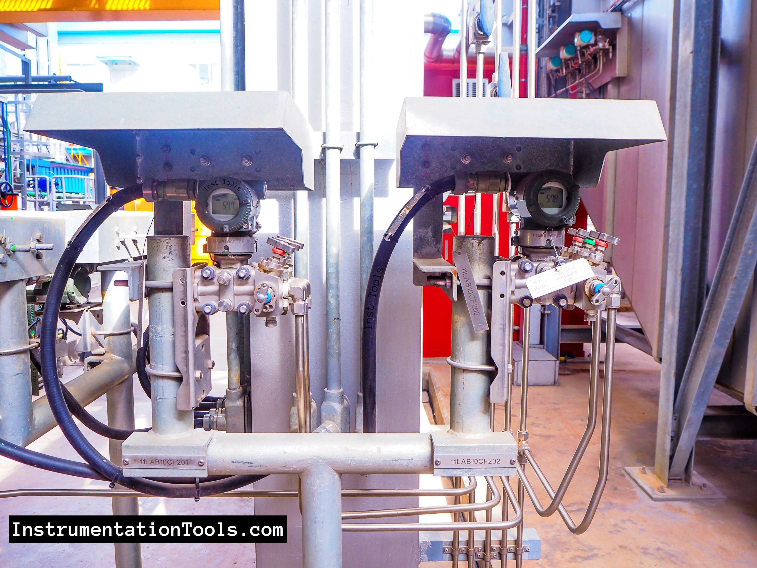
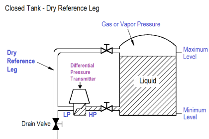
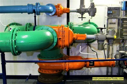
A dry leg DP type level transmitter was installed in a tank that stores water. One leg of the transmitter i.e. high-pressure side is connected to the tank bottom while the other leg i.e. low-pressure side is connected to the top of the tank.

The LP side is dry leg type. The connection is from the top of the tank because the tank receives the water and then supplies the water as per the process need.

Due to this, the tank undergoes pressure change and hence LP side of the transmitter is connected to the top of the tank for reference pressure purposes.

Root Cause Analysis of Differential Pressure Level Transmitter

Preventive maintenance was taken for the DP type level transmitter. The level reading before the job was 92 %. The level transmitter was working perfectly. During the preventive maintenance job, the level transmitter was isolated.

The response of the level transmitter was checked. Then after the flushing job, the level transmitter was taken in line. After the preventive maintenance job, the level transmitter was showing 70 % level only. While in the level gauge, the level was 93 %.

So, on a doubt basis of the level gauge, the level gauge was taken for the maintenance job. But still, after completion of the maintenance job on the level gauge, the level was the same i.e. 93 %. But still level transmitter was showing 70 %. After the maintenance job on the level transmitter, the level transmitter was showing a 93 % level.

So what can be the probable reason for water coming out of the LP side of the level transmitter after the Preventive maintenance job?

Root Cause Analysis of Level Transmitter

Probable Problem 1: Actual level was 70 % and after the preventive maintenance job, the level transmitter started showing an ok value.

While confirming the reading with the level gauge, the level was found 93 %. Also, the level gauge was checked and found ok. So this possibility was ruled out.

Probable Problem 2: The level transmitter became faulty

During the preventive maintenance job, the level transmitter’s response was checked. The response of the level transmitter was ok.

Probable Problem 3: Problem in the root valve opening

Both the root valves were found open during checking after the problem was encountered. Both the root valves were found open.

Probable Problem 4: Issue in manifold

Manifold checked after the problem was encountered. Both the isolation valves, vent valves, and equalization valve were found in ok condition.

Probable Problem 5: Leakage in the impulse tubing of the level transmitter

Leakage was checked after the problem was encountered. No leakage was found.

Observations

Observations after taking level transmitter for maintenance job again:

  1. The actual level was the same.
  2. Level transmitter’s response checked. Found ok.
  3. Level transmitter’s both root valves checked. Found ok.
  4. Level transmitter’s manifold valve’s condition checked. Found ok.
  5. The level transmitter’s tube was checked for any leakages. Found no leakage.
  6. While opening the LP side vent plug, found water coming out of the LP leg. LP side flushed and taken inline. Level transmitter started showing 93%.

What went wrong?

As per the technician who did the job, the following activities were done. During the level transmitter preventive maintenance job, the level transmitter was isolated from the root valves.

Then the level transmitter’s response was checked using the pressure calibrator. The response was found ok. Both HP leg and LP leg were flushed and then the transmitter was taken inline.

But while filling the preventive maintenance checklist, the technician observed that he missed zero checking procedures. So he opened the equalization valve and then closed the isolation valves from the manifold.

So in this process, the water from the HP side went to the LP side. After checking zero which was found ok. Then transmitter was taken inline. Now due to the water on the LP side, the level transmitter started showing low values.

If you liked this article, then please subscribe to our YouTube Channel for Instrumentation, Electrical, PLC, and SCADA video tutorials.

You can also follow us on Facebook and Twitter to receive daily updates.

Read Next:

  • Level Indicators Working Principle
  • Transparent & Reflex Level Gauge
  • Calculate Current 4-20 mA
  • Level Gauge Design
  • Types of Level Gauges
Don't Miss Our Updates
Be the first to get exclusive content straight to your email.
We promise not to spam you. You can unsubscribe at any time.
Invalid email address
You've successfully subscribed !

Continue Reading

Ultrasonic Level Transmitter Working Principle
Level Measurement with Dry leg and Installed Below Tapping Point
Carbamate Plunger Pump Packing Problems Eliminated
Effects of Symmetric and Asymmetric Capillary Tube Pressure Measurement
Compressor Anti-Surge Control near-miss incident
Rotary Level Switch Working principle Animation
Share This Article
Facebook Whatsapp Whatsapp LinkedIn Copy Link
Share
1 Comment
  • Tejas says:
    February 4, 2023 at 12:26 pm

    We are always facing this issue with DP type level transmitter. We flushed the high level inclined ss line so we get level proper. is there any other solution.

    Reply

Leave a Reply Cancel reply

Your email address will not be published. Required fields are marked *

Stay Connected

128.3kFollowersLike
69.1kFollowersFollow
210kSubscribersSubscribe
38kFollowersFollow

Categories

Explore More

Condensate Pump Frequent Wrecks Threatens Long Plant Outages
Compressor Cracked Shaft Spacers
Non-Contacting Radar Level Transmitter Working Principle
Hydrostatic Tank Gauging (HTG)
what is a Bubbler System?
Problem with Choked Control Valve with Whisper Trim Cage
Pulverizer Electrical Problem Solved
Which Instrument is at Fault in this System?

Keep Learning

Closed-tank-DP-Level-Transmitter-with-cleaning-leg-Calibration

Closed tank DP Level Transmitter with cleaning leg Calibration

Thermocouple Extension Lead Problem

Thermocouple Extension Lead Problem

Ultrasonic Level Switch Principle

Ultrasonic Level Switch Principle

Interface Level Measurement Selection Guide

Interface Level Measurement Selection Guide

Ultrasonic-Level-Transmitter-Animation

Ultrasonic Level Transmitter Animation

Non‐contact RADAR Level Transmitter Pulse

Non Contact RADAR Level Transmitter Principle, Limitations, Design, Installation and Calibration

4 way solenoid valve root cause

Safety Liquid Ammonia Disconnect threatens NH3 Vapor Spill

Electrical Engineering Problems - Root Cause Analysis

30 Electrical Engineering Problems – Root Cause Analysis

Learn More

What is Chromatography

What is Chromatography ?

Differential Pressure Transmitter Manifold

Field Instrument Calibration Errors

Digital Electronics Multiple Choice Questions

Flip Flops Objective Questions – Part 3

Instrumentation Cyber Security

Instrumentation Cyber Security Glossary

Custody Transfer Meter Checks

Checklist for Custody Transfer Meters: Mass Flowmeter

Transformer Protection using fire water spray system

Fire Water Spray Systems Principle

phototransistor symbols

Phototransistor Working Principle

Types of Fire Detectors

Types of Fire Detectors

Menu

  • About
  • Privacy Policy
  • Copyright

Quick Links

  • Learn PLC
  • Helping Hand
  • Part Time Job

YouTube Subscribe

Follow US
All rights reserved. Reproduction in whole or in part without written permission is prohibited.
Welcome Back!

Sign in to your account

Username or Email Address
Password

Lost your password?