Inst ToolsInst ToolsInst Tools
  • Courses
  • Automation
    • PLC
    • Control System
    • Safety System
    • Communication
    • Fire & Gas System
  • Instrumentation
    • Design
    • Pressure
    • Temperature
    • Flow
    • Level
    • Vibration
    • Analyzer
    • Control Valve
    • Switch
    • Calibration
    • Erection & Commissioning
  • Interview
    • Instrumentation
    • Electrical
    • Electronics
    • Practical
  • Q&A
    • Instrumentation
    • Control System
    • Electrical
    • Electronics
    • Analog Electronics
    • Digital Electronics
    • Power Electronics
    • Microprocessor
  • Request
Search
  • Books
  • Software
  • Projects
  • Process
  • Tools
  • Basics
  • Formula
  • Power Plant
  • Root Cause Analysis
  • Electrical Basics
  • Animation
  • Standards
  • 4-20 mA Course
  • Siemens PLC Course
Reading: Oxidation-Reduction Potential (ORP) Sensor Calibration Procedure
Share
Font ResizerAa
Inst ToolsInst Tools
Font ResizerAa
  • Courses
  • Design
  • PLC
  • Interview
  • Control System
Search
  • Courses
  • Automation
    • PLC
    • Control System
    • Safety System
    • Communication
    • Fire & Gas System
  • Instrumentation
    • Design
    • Pressure
    • Temperature
    • Flow
    • Level
    • Vibration
    • Analyzer
    • Control Valve
    • Switch
    • Calibration
    • Erection & Commissioning
  • Interview
    • Instrumentation
    • Electrical
    • Electronics
    • Practical
  • Q&A
    • Instrumentation
    • Control System
    • Electrical
    • Electronics
    • Analog Electronics
    • Digital Electronics
    • Power Electronics
    • Microprocessor
  • Request
Follow US
All rights reserved. Reproduction in whole or in part without written permission is prohibited.
Inst Tools > Blog > Analyzers > Oxidation-Reduction Potential (ORP) Sensor Calibration Procedure

Oxidation-Reduction Potential (ORP) Sensor Calibration Procedure

Last updated: September 14, 2016 10:58 pm
Editorial Staff
Analyzers Calibration
3 Comments
Share
3 Min Read
SHARE

ORP stands for Oxidation-Reduction Potential. In practical terms, it is a measurement to oxidize contaminants. It’s as simple as that

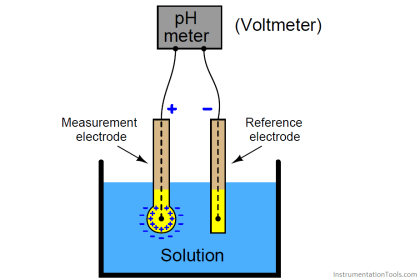
The Oxidation-Reduction Potential (ORP) Sensor measures the ability of a solution to act as an oxidizing or reducing agent. Use the ORP Sensor to measure the oxidizing ability of chlorine in swimming pools or to determine when the equivalence point has been reached in an oxidation-reduction reaction.

Checking ORP is a simple method to monitor the effectiveness of a sanitizer or the quantity of anti-oxidants in a liquid. In generalized terms for humans, a higher ORP is better for outside of the body, while a lower ORP is preferred for consumption due to the high anti-oxidant value.

The oxidation/reduction potential is the electrometric difference measured in a solution between an inert indicator electrode and a suitable reference electrode. The electrometric difference is measured in millivolts and is temperature dependent.

Calibration or Verification Procedure:

1. Allow the calibration standard (a Zobell solution: read the warning on the label before use) to equilibrate to ambient temperature.

2. Remove the probe from its storage container and place it into the standard.

3. Select measurement ‘mode.

4. Wait for the probe temperature to stabilize, and then read the temperature.

5. If the instrument is to be calibrated, do Steps 6 and 7. If the instrument calibration is to be verified, then go to Step 8.

6. Look up the millivolt (mv) value at this temperature from the millivolt versus temperature correction table usually found on the standard bottle or on the standard instruction sheet. You may need to interpolate millivolt value between temperatures. Select “calibration mode”, then “ORP”. Enter the temperature-corrected ORP value into the instrument.

7. Select measurement mode. The readings should remain unchanged within manufacturer’s specifications. If they change, re-calibrate. If readings continue to change after re-calibration, try a new Zobell solution or consult manufacturer. Go to Step 9.

8. If the instrument instruction manual states that the instrument is factory calibrated, then verify the factory calibration against the Zobellsolution. If they do not agree within the specifications of the instrument, try a new Zobell solution. If it does not agree, the instrument will need to be re-calibrated by the manufacturer.

9. After the calibration has been completed, rinse the probe with deionized water and store the probe according to manufacturer’s instructions.

10. Record the calibration information on the calibration log sheet.

Don't Miss Our Updates
Be the first to get exclusive content straight to your email.
We promise not to spam you. You can unsubscribe at any time.
Invalid email address
You've successfully subscribed !

Continue Reading

The Principle of Dead Weight Pressure Tester
Ultrasonic Level Transmitter Principle, Limitations, Calibration and configuration
Transmitter Calibration Procedure
Impulse Line Pressure Testing Procedure
Pig Signalling Switches Functional Testing
Calibration of Pyrometers using Black Body
Share This Article
Facebook Whatsapp Whatsapp LinkedIn Copy Link
Share
3 Comments
  • ray says:
    October 3, 2015 at 10:51 pm

    I used to be very happy to find this web site. I wanted to thanks for your time for this wonderful read !!

    Reply
  • lakhan says:
    February 16, 2016 at 9:22 am

    I dont have word for thanking you.my all questions and problems solves after see this site. This is amazing and its language is very simple for understanding. I have one question how to measure level by pressure difference in mmh2o.

    Reply
    • S Bharadwaj Reddy says:
      February 16, 2016 at 4:56 pm

      Hello Lakhan, Plz Click Here For Measurement of Pressure Difference in mmh20. Thanks

      Reply

Leave a Reply Cancel reply

Your email address will not be published. Required fields are marked *

Stay Connected

128.3kFollowersLike
69.1kFollowersFollow
210kSubscribersSubscribe
38kFollowersFollow

Categories

Explore More

Control Valve Stroke Test Procedure
Online Gas Chromatograph Principle
Basics of Total Organic Carbon (TOC) Analyzers
Hair Hydrometer Principle
DP type Flow Transmitter Preventive Maintenance and Calibration
Temperature Sensor calibration procedure
Moisture and Dew Point Analyzer Problems and Troubleshooting Tips
What is a Dry Block? – Parts of the Temperature Calibrator

Keep Learning

History of Measurement

History of Measurement

Gas-chromatograph-Working-Principle

Gas chromatograph Working Animation

toroidal conductivity probe principle

Electrodeless Conductivity Probes Principle

Oxygen Measurement using Tunable Diode Laser System

Tunable Diode Laser Analyzer Working Principle

DO Analyzer Working Principle

Dissolved Oxygen Analyzer Working Principle

pH sensor calibration procedure

calibration potentiometer for simulating the millivoltage output

Temperature Standards

Infrared Flue Gas Analyser

What is Infrared Flue Gas Analyzer? – Working Principle

Learn More

Power Electronics Objective Questions

Type E Chopper Objective Questions

CNC Programming - Definition, Types, and Tips

CNC Programming – Definition, Types, and Tips

Circuit Control Devices Multiple Choice Questions

Circuit Control Devices Multiple Choice Questions & Answers

Electrical Machines Questions and Answers

Energy Conversion Quiz

What is a Memristor

What is a Memristor? Principle, Advantages, Applications

Process Plant Risk and Safety Management

Safety Roles & Responsibilities of Process Engineering (Detail Design)

Hydrogen sulfide gas

Hydrogen Sulfide Gas (H2S)

Complementary Split Range Control

What is Complementary Split Range Control (CSRC)?

Menu

  • About
  • Privacy Policy
  • Copyright

Quick Links

  • Learn PLC
  • Helping Hand
  • Part Time Job

YouTube Subscribe

Follow US
All rights reserved. Reproduction in whole or in part without written permission is prohibited.
Welcome Back!

Sign in to your account

Username or Email Address
Password

Lost your password?