FOUNDATION Fieldbus devices (also called nodes) are addressed by an eight-bit binary number when functioning on an H1 segment.
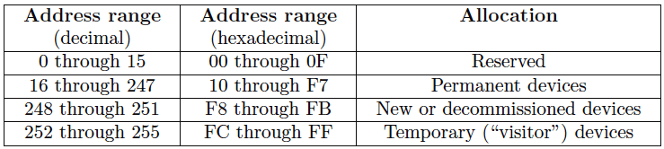
This binary number field naturally supports a maximum addressing range of 0 to 255 (decimal), or 00 to FF hexadecimal.
This address range is divided into the following sub-ranges by the Fieldbus Foundation:
Devices are usually assigned addresses to function on the segment by the host system (typically a DCS with FF capability), although it is possible to order FF instruments pre-configured at the factory with addresses specified by the customer upon order.
Host systems are generally configured to automatically determine device addresses rather than require the technician or engineer to manually assign each address. This makes the commissioning process more convenient.
The maximum number of “permanent” devices (installed field instruments) allowed on an H1 segment for operational reasons is 32, and as you can see the addressing scheme offers far more valid addresses than that.
One of the many tasks given to a segment’s Link Active Scheduler (LAS) device is to probe for new devices connected to the segment.
This is done on a one-at-a-time basis, with the LAS sequentially polling for uncommissioned addresses within the valid address range.
Obviously, this can be a waste of time with only 32 addresses capable of active service at any given time and over 200 valid address numbers.
A practical solution to this problem is to specify an “unused” address range for the LAS to skip, so it does not waste time probing for devices (nodes) within a certain range.
This address range is specified as a set of two numbers: one for the First Unused Node (abbreviated FUN), and another specifying the Number of Unused Nodes (abbreviated NUN).
For example, if one wished to have the LAS on a particular H1 segment skip device addresses 40 through 211, one would configure the FUN to equal 40 and the NUN to equal 172, since the address range 40 through 211 is one hundred seventy two addresses (inclusive of both 40 and 211).
Even with a maximum operational limit of 32 devices to an H1 segment, it is rare to find segments operating with more than 16 devices. One reason for this is speed: with additional devices requiring time to broadcast and process data, the total macrocycle time (the time period between guaranteed delivery of the same process data from any one device – the determinism time) must necessarily increase.
According to the Fieldbus Foundation’s engineering recommendations guide, there must be no more than twelve devices on a segment (including no more than two final control elements) in order to achieve a 1-second or less macrocycle time.
For half-second update times, the recommended maximum is six devices (with no more than two final control elements).
For quarter-second update times, the limit drops to a total of three devices, with no more than one final control element. Macrocycle time is essentially dead time, which is worse than lag time for any form of feedback control.
When controlling certain fast processes (such as liquid pressure or flow rate), dead times on the order of one second are a recipe for instability.
Another limitation to the number of operational addresses on an H1 segment is current draw. FF devices draw 10 mA of current minimum.
A FF segment with sixteen parallel-connected devices would see a total current of 160 mA minimum, with a more realistic value being in excess of 300 mA.
In addition to network addresses, each FF device bears an absolutely unique identifier (a 32- byte binary number) to distinguish it from any other FF device in existence.
This identifier serves much the same purpose as a MAC address on an Ethernet device. However, the identifier field for FF devices allows a far greater instrument count than Ethernet: 32 bytes for FF instruments versus 48 bits for Ethernet devices.
While the Ethernet MAC address field only allows for a paltry 2.815 × 10¹⁴ unique devices, the FF identifier allows 1.158 × 1077 devices!
The distinction between a FF device’s network address and the device’s identifier is virtually identical to the distinction between an Ethernet device’s IP address assigned by the end-user and its MAC address number assigned by the manufacturer.
This identifier value is usually expressed as 32 ASCII-encoded characters for brevity (one alphanumeric character per byte), and is subdivided into byte groups as follows:
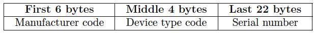
For example, the identifiers for all Fisher brand devices begin with the first six characters 005100. The identifiers for all Smar devices begin with the characters 000302.
The identifiers for all Rosemount brand devices begin with 001151. A typical identifier (this particular one for a Fisher model DVC5000f valve positioner) appears here:
005100 0100 FISHERDVC0440761498160
Normally, these identifiers appear as 32-character strings, without spaces at all. I have inserted spaces within this string to make the character groupings easier to see.