Burner Management System or BMS (not to be confused with building management system from another industry!) is a mechanism that monitors fuel burning equipment during start-up, shutdown, operation and transient conditions.
It must be designed to present the status of all fuel burning equipment to the operator’s interface in a concise format.
Burner Management System
The BMS primary tasks are to automatically initiate a safe operating or shutdown sequence to prevent an explosion from occurring inside the furnace hence, protecting equipment from damage and most significantly, personnel from injuries or death.
The Burner Management System is essentially an interlock switch which permits firing of a boiler at any load and shuts down the fuel sources shall unsafe process conditions occur.
BMS also goes by different names. In my previous power plant, it is called as FSSS or Furnace Supervisory Safeguard System which does the same duty.
A BMS is required in line with the inclusions of NFPA 85, Boiler and Combustion Systems Hazards code.
The citations are as follows:
a) Single burner boilers, multiple burner boilers, stokers and atmospheric fluidized bed boiler with a fuel rating of 3.7MWt (12.5 million Btu/hr) or greater.
b) Pulverized fuel systems at any heat input rate
c) Fired or unfired steam generators used to recover heat from combustion turbines [heat recovery steam generators (HRSGs)] and other combustion turbine exhaust systems at any heat input rate.
The purpose of the Code stated is to ensure a safe process by establishing minimum requirements for the design, installation, operation and maintenance of boilers, pulverized fuel systems, HRSG as well as their associated systems for fuel burning, air supply and combustion product removal.
The code requires the unison of operating procedures, control systems, interlocks and structural design. The goal is to avert the most common contributor of explosions in the past, human error it is.
Purge Control and Oil Leak test
Purging is obligatory before ignition of the first burner in order to clear any combustibles which may have been accumulated in the boiler and its components.
The multiple-burner Purge Rate air flow as described on the NFPA code shall fall between 25%-40% range of designed full load mass airflow. This air flow has to be maintained from purge completion through light-off and initial loading. If in the middle of purging, the air flow has decreased below the nominal value, the purging time must be reset.
The process must be completed on the specified time under the definite air flow condition. This time we are speaking of must not be any lesser than 5 minutes or the time it takes for five volume changes of the boiler enclosure whichever is longer.
The total mass airflow is calculated with a weighted Primary Air and Secondary Air flow ratios expressed under ideal gas conditions as Nm3/s. In the case of my current Plant, the weighted ratio values for PA and SA flow are….
Operational leak test of the fuel header piping must also be performed while maintaining the required purging air flow. Purging and Oil leak test must be successfully satisfied before the fuel header will be placed in operation.


Figure 1: Sequential flowchart of Boiler Purge and Oil leak test. Ellipses indicate optimal values to be figured out during design stage or commissioning proper.
Figure 1 summarizes the purge and oil leak test events on a somewhat flowchart format. The goal is to pressurize oil group lines for leak testing and check if the holding pressures are sustained. If the pressure on either group rises, the main shut-off valve must have leakages on it as it allows passage of residual oil.
On the contrary that the pressure decreases, there must be some leakage in between the piping of the main shut-off and return valves or in the return valves themselves. We can better visualize the flow of oil using
Figure 2 below. The purge process can start after the HMI button is pressed for as long as it maintains the nominal flow rate. It does not need to wait for the leak test to be finished simply put, the two processes can be performed simultaneously.
If both processes are completed successfully, the Master Fuel Trip (MFT) reset button can be already pressed and all the MFT relays will be energized. We can now proceed in lighting off the first burner!

Figure 2: A tidbit of Start-Up burner P&ID.
Interlock System Diagram
I would really love to share our actual interlock diagram implemented at the Plant but let’s just make use of the standard extracted from the NFPA 85 document.
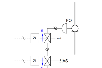
Individual igniter shutdown sequences shall occur during the following situations:
a) Loss of igniter flame being constantly monitored by robust flame scanners.
b) Igniter oil (or gas) pressure low via pressure switches installed on the lines.
c) Igniter atomizing air pressure low via pressure switches on pneumatic lines.
Atomizing air is what transforms the fuel oil into very fine particles through the use of engineered nozzles. Just like how you sprinkle water to the Bermuda grass on your lawn with a specialized hose nozzle, the oil in this form will enable its full combustion potential.
Master fuel trip, MFT as we keep on mentioning is the term we use to kill all fuel sources which cause combustion, not only limited to start-up oil igniters but also including the coal conveying systems. All pneumatic shut-off valves shall close, if possible at lightning speed, and all coal conveyor VFDs must stop.
It must be important to understand that an MFT does not necessarily mean that we are shutting down the entire boiler. The boiler draft system can still function despite an MFT. This is to maintain air circulation and provide ventilation. However if one of the draft sources has ceased from operating, it is mandatory to execute an MFT.
I appreciate the design of my plant’s interlock set-up because all MFT sources are instrumentation-based. This means that the system checks the individual draft fan’s pressure outputs instead of looking at its individual running status from the switchgears, which totally makes sense because running an equipment does not guarantee that it is producing the required process values.
I would also like to talk about what I believe are the most overlooked causes of MFT:
1) 3-time unsuccessful Ignition attempts
During lighting off the first burner, BMS tracks the attempts taken before establishing the flame. If after three consecutive attempts, the flame scanner is not registering any signs of flame inside the furnace, then an MFT must act.
This can be ground for further investigation as to why the burner has failed to light during normal operation but if we are experiencing this during commissioning stage, considerations can be made given that it will be properly tuned both in the field and the DCS logic.
2) Loss of all fuels
If during the lighting off sequence of the second burner, the first burner has lost its flame, an MFT shall again take place. This means that the furnace has an absence of ignition and must be purged again to prevent combustible debris from exploding.
Of course this situation is also applicable when multiple fuel sources shutdown while in the middle of a sequence of starting another fuel system, which can be a very rare case as the blue moon.

Figure 3: Interlock system diagram for multiple burners. Excerpt from section 6.4.1.2.1 of NFPA 85.
Control Systems Hardware / Software Requirements
The burner management system must be provided with independent logic, independent logic solving hardware, independent input/output systems and independent power supplies. It shall be an autonomous device in a way that it is functionally and physically separate from other logic systems.
Signals and the manually operated devices such as push buttons on the operator’s console which would initiate mandatory Master Fuel Trips must be hardwired. This requirement is one of the reasons why modern coal fired power plants are still being built on the foundation of conventional hardwired analog and discrete signals.
Provisions for digital I/O interfaces such as FieldBus and Profibus or even wireless are still limited. We cannot see legacy wires retiring any time soon simply because of its proven fast reaction and reliability.
System redundancy is already a norm in DCS or PLC these days but it is worth noting that in a BMS, the whole system must be capable of hot-standby (seamless) switching shall a failure occur on the power supply or the network communication switches.
The typical set-up of redundancy is through the levels of primary/secondary controller CPUs, dual redundant ring network topology and dual UPS. During Site Acceptance Tests (SAT) the functionality of hot-standby for these levels must be duly tested to be functioning.
“No single component failure within the logic system shall prevent a mandatory master fuel trip.”

Figure 4: Streamlined Plant Data Highway. All components are powered by redundant UPS and are not shown for simplicity. BPS is Boiler Protection System while BCS is Boiler Control System.
Watchdog circuits, hard-wired on MFT relay panels and soft I/Os in the DCS is also a requirement to prove the integrity that the entire BMS is healthy. Healthy means that there is a continuous power supplied to the relays which are normally energized and the connection among the controller CPUs is not ceased.
Normally a function block is used to generate random signals and be distributed on each individual controller CPU. Take for example the algorithm called “heartbeat” in an Ovation™ DCS. This algorithm block’s task is to broadcast a randomly changing signal to all controller CPUs.
Each controller CPU then detects that the signal it receives from the other CPUs in the control network is continuously varying which indicates an “alive” state. The moment one CPU has recognized any received signal broadcast halted from varying within a very short amount of time, it will act on instinct to generate an MFT demand to occur.
“Failure of the logic system shall require a fuel trip for all equipment supervised by the failed logic system.”
Field Instrumentation
In a Supreme Court where the DCS is the chief justice and three field instruments are associate justices, a voting is required to convict a murder fuel trip, I mean Master Fuel Trip! To achieve this, two instruments must be able to distinguish a process trip point before initiating an MFT.
This is known as the 2 out of 3 or 2oo3 voting. The BMS supervising instruments also must be checked for its signal propagation quality. If in any case that an instrument turns bad quality, it will already be considered as one trip condition.
The burner management system interlock and alarm functions shall be initiated by one or more of the following:
1) One switch or transmitter dedicated to the burner management system.
2) Voting logic derived from two or more switches or transmitters.
I remember a scenario when the commissioning operators of my plant are trying to shut down the fuel igniters purposely by emptying the steam drum and cause a drum level low-low condition. They did not know that by doing so will also empty the condensate pots as well as the impulse filled lines of the 2oo3 level transmitters.
As a result, the analog current value fell below the sensor quality limit monitoring of the DCS, say 3.6mA instead if the usual 4mA. This event triggered also the drum level high-high condition and eventually shut down the draft system making the boiler trip unintentionally.
I can conclude this primer with the sequential flowchart of the actual operation of a Start-up burner sequence but I decided to include them on a follow-up article which will be published some other time.
Editor’s notes: This article was based on the 2015 edition of NFPA 85: Boiler and Combustion Systems Hazard code. The editor also drew inspiration from Jerry Gilman’s Boiler Control Systems Engineering ISA handbook. The written article is very limited and covers only the editor’s personal understanding as well as experience of the subject. If the reader wishes to have a copy of full NFPA 85 Code, the editor would be much obliged to send it through an appreciation comment below.
Ovation™ is a registered trademark of Emerson Process Management.
P.S. Weighted Ratio of our Plant PA and SA flows are still to be determined. The editor keeps on forgetting to check them on the DCS Signal Diagrams!
Author: Jeremiah Cayondong


Great article..covering all the major points
1. However , I would like the article to cover the Energised to trip concept vis a vis deenergised to trip concept which is fundamental for BMS design.
2. Also if we have balanced draft furnace then the implosion protection also requires to be covered as this interlock needs close coordination with FD/ID fan logic.
3. Regarding “3 unsuccessful light up trip”, as unburnt oil
could have accumulated, a purging is needed to avoid sudden puff inside the furnace.
4.Loss of all fuel is basically covering a condition of all burners and Mills and all ignitors off condition after boiler light up to tackle the high negative pressure inside thee furnace that arises after loss of all fuel.The flame failure trip also will follow anyhow.
5. The FD ID and PA fan switchgear feedback is quicker and cannot be substituted by airflow signals which will introduce time delay.
As draft high and draft low conditions are triggering MFT without time delay, this is very important.
Sir, Explain about the flame scanner