What is Flue Gas?
Flue gas is a mixture of various gases obtained by the burning of fuel materials at the boiler furnace in the presence of excess air or oxygen in power plants and vented to the atmosphere via ducts and chimneys.
Flue gas is also known as exhaust gas or stack gas
Composition of Flue Gas
| Composition | Mol % Coal-fired | Mol % Gas Fired |
| H2O | 8 | 8 |
| Nitrogen | 73 | 76 |
| Carbon dioxide | 14 | 4 |
| Oxygen | 3.5 | 12 |
| Hydrogen sulfide | 0.05 | 0 |
Flue Gas Parameter
| Parameter | Coal-fired | Gas fired |
| The flow rate in m3 per hour | 2400 | 2850 |
| The temperature in Degree Celsius | 40 | 40 |
| Pressure in kg/cm2 | 1.1 | 1.1 |
- The complete combustion of the fuel and the analysis of flue gas is a very important consideration in all power plant stations.
- The term complete combustion defines a total conversion of the carbon present into carbon dioxide (CO₂), hydrogen into H₂O, and sulfur into SO₂.
- The measurement of CO₂ in flue gas gives an idea of how effectively the combustion has taken place in the boiler.
- To represent complete combustion the absolute value of CO₂ is not found.
- An indication is available for total fuel consumed and CO2 variation with respect to time.
- To measure CO2 present in flue gas, the principle of thermal conductivity is considered.
- The thermal conductivity of CO₂ is quite low compared to other principal constituents of flue gases namely N₂, O₂, H₂, and CO.
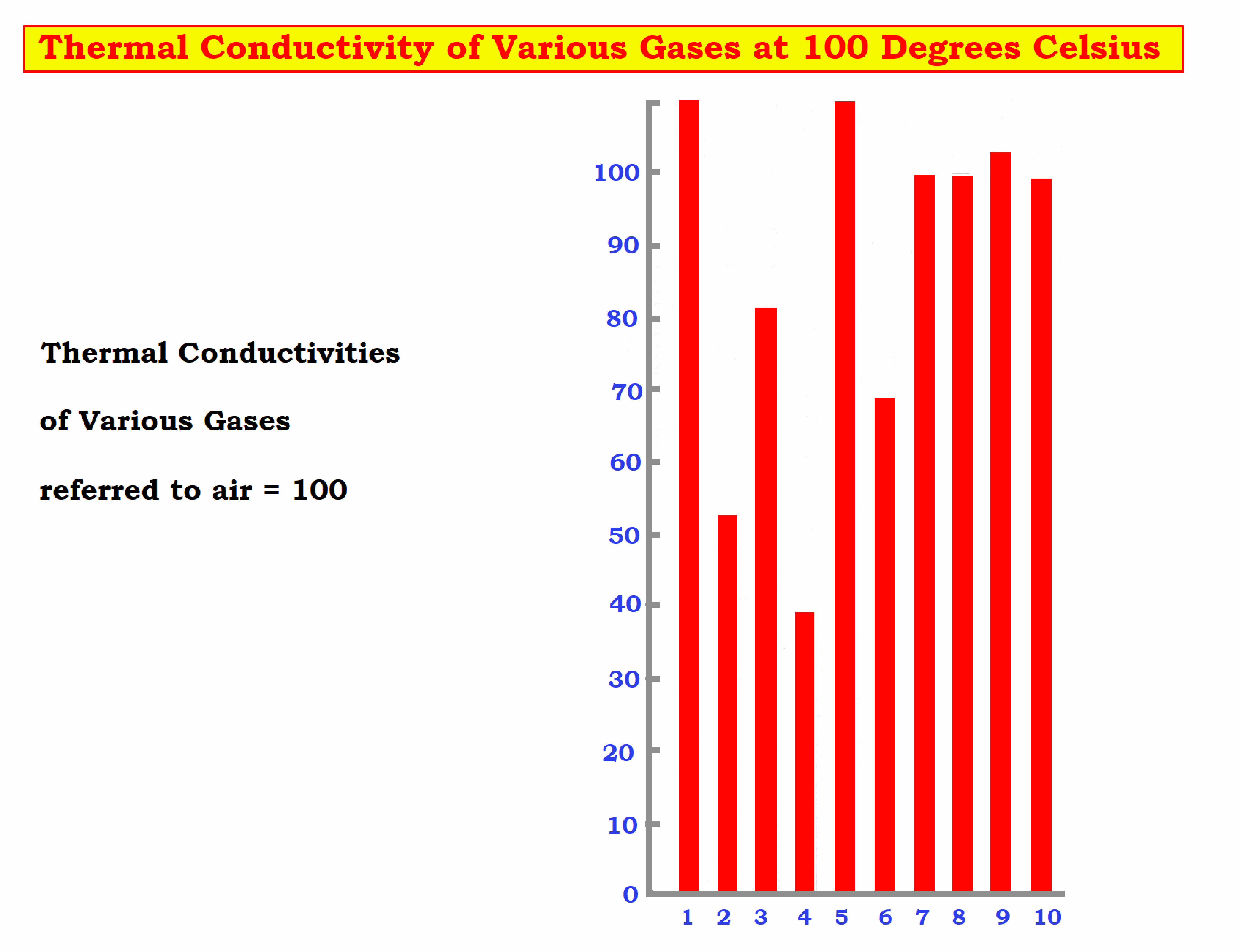
| Serial | Components | Symbol |
| 1 | Methane | CH4 |
| 2 | Benzene | C6H6 |
| 3 | Ammonia | NH3 |
| 4 | Sulphur Dioxide | SO2 |
| 5 | Hydrogen | H2 |
| 6 | Carbon Dioxide | CO2 |
| 7 | Carbon Monoxide | CO |
| 8 | Nitrogen | N2 |
| 9 | Oxygen | O2 |
| 10 | Air | – |
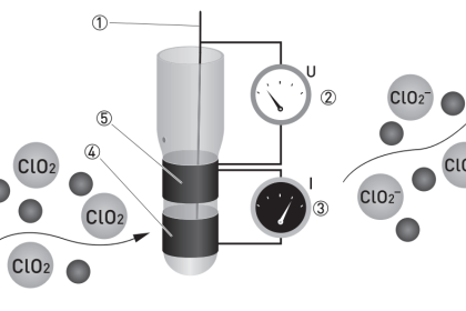
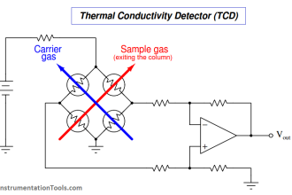
To determine the CO₂ content in flue gas, the flue gas is allowed to pass through two test cells and the air is passed through two reference cells in which they flow around stretched platinum resistance wire electrically heated up to 100°C.
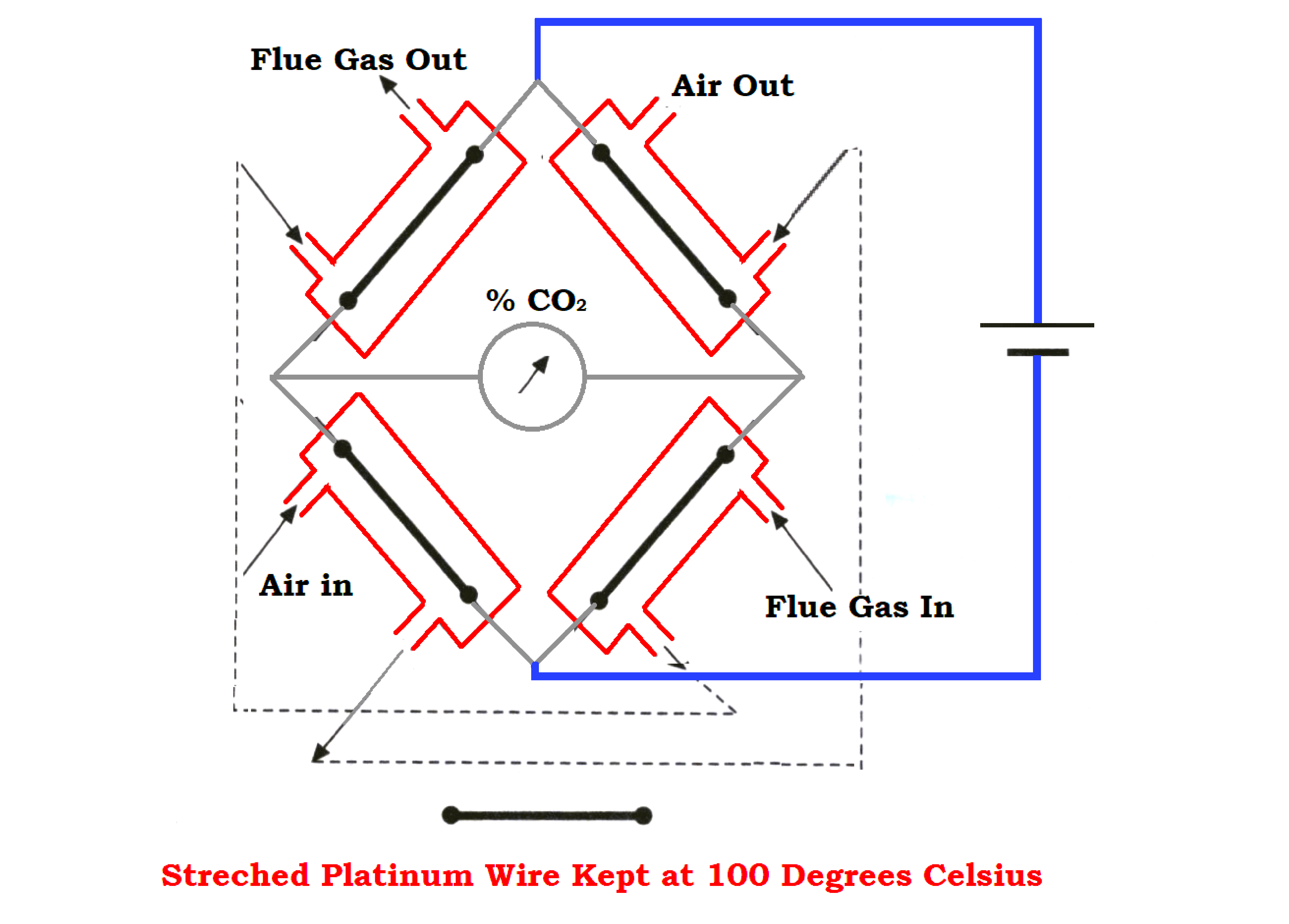
- The test gas and reference air will transfer the heat generated to the cell walls as per the individual conductivity of that gas.
- The conductivity and CO2 content are inverse proportion to each other when the flue gas conductivity decreases as CO₂ content increases and vice versa. During the same period the temperature and resistivity of the heated wires increases.
- The bridge unbalance is measured and the instruments are calibrated in the percentage of carbon dioxide by their volume.
- For instance, 20% CO₂ in flue gas will increase the temperature of the heated wires by approximately 6°C and thereby increase the electrical resistance by 0.2 ohms.
- The thermal conductivity of Carbon Dioxide is 0.0166 W/(m·K).
How do you Calculate Carbon Dioxide in Flue Gas?
- Let us assume biomass of 100 kg.
- This calculation confirms that all the carbon is burned, meaning no carbon is found in burnt ash.
- In case of any unburned carbon, it must be subtracted from the value of carbon. There is no entry of N2 in flue gas or the system.
- Carbon dioxide from biomass = 4.33 × 0.224 = 0.97 m3.
- Net dry flue in gas 1 kg of wood = 4.872 m3.
- Therefore percentage of Carbon-di-Oxide (%CO2) is 0.97/4.872 = 19.91 %.
Assuming stoichiometric combustion (0% O2).
- For 20 % excess air = 16.6 % CO2
- For 40 % excess air = 14.2 % CO2
- For 50 % excess air = 13.27 % CO2
Which instrument is used to measure carbon content in flue gas?
Carbon content in flue gas is measured using an Orsat apparatus gas analyzer. It is laboratory equipment for analyzing flue gas samples for oxygen, CO, and CO2 content.
What do you mean by thermal conductivity?
Thermal Conductivity is defined as the material’s ability to transfer heat. It is the heat energy transferred per unit time and the unit surface area divided by the temperature difference.
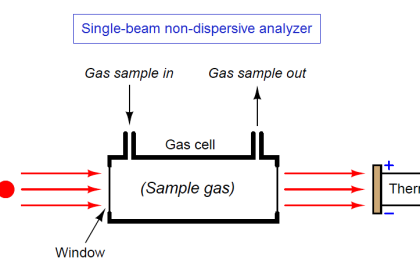
What is the principle of a thermal conductivity analyzer?
The thermal conductivity of a gas analyzer is a measure of gas concentration by using the difference in thermal conductivities between two gas components.
In the gas detector, there is a reference chamber and a measuring chamber in each of which a thin platinum wire is stretched.
How is the thermal conductivity of gas measured?
All gases have their thermal conductivity. The thermal conductivity of a gas is measured using a sensor that employs four matched filaments that change their resistance according to the thermal conductivity of the gas passing over it.
If you liked this article, then please subscribe to our YouTube Channel for Electrical, Electronics, Instrumentation, PLC, and SCADA video tutorials.
You can also follow us on Facebook and Twitter to receive daily updates.
Read Next:
- Turbine and Compressor System
- Steam Circuits in Power Plants
- Furnace Draft Control System
- Turbine Steam Pressure Control
- Working Principle of Steam Ejector