Measurement of Flow
- To calculate the efficiency of the boiler the coal required for combustion must be measured.
- This measured value can also be used for combustion control of the boiler.
- This is not a straight measurement as it is done for liquid or gaseous fuel.
What are the Methods involved in Flow Measurement?
The three common methods available are
The Indirect Measurement of Coal Bunker Level
- Coal to the power plant is delivered through trucks or rail wagons and through ships in some cases if the plant is near the sea or ocean.
- From the coal yard, it is delivered through belt conveyors.
- The plant must have sufficient space for storing and proper mechanical equipment for lifting from the coal yard to the bunker.
- These bunkers called storage bins are installed at a higher elevation that allows the coal to feed to the boiler furnace using gravity.
- The level of coal in the bunker must be recorded at regular intervals, this level difference is converted into volume to measure the average flow rate.
- Totalling of the required flow rate of fuel must be done daily after the operation and the average flow rate can be calculated.
- Though such measurements cannot be used for continuous control purposes, the information can be very well used for boiler efficiency calculations.
Measurement using Load Cells
- The coal hoppers are fitted with load cells and then fed to the boiler system.
- The weight measurement is taken when the hopper is filled and then dumped into the feeding conveyor belt.
- This cycle is repeated continuously, and the measured weight is divided by the time cycle to calculate the average feed rate of fuel.
- This method of measurement gives more accurate results when compared to bunker-level measurement.
Measurement by Belt Weighing
- The flow rate of coal is measured via a belt conveyor when the coal is fed to the boiler furnace for combustion.
- The coal is weighed by load cell arrangement in a conveyer belt between two adjacent rollers.
- The conveyor speed must be measured to calculate the flow rate.
- The feed rate of all belt weighing feeders is a function of the belt speed and the belt load.
- The speed of the belt is normally expressed in terms of meters per minute, and the belt load is defined as kilograms per meter.
- The feed rate is directly proportional to the belt load for constant-speed belt feeders.
Feed Rate = Belt Speed X Belt Load
Liquid Flow Measurement
Furnace oil or tar oil is used as fuel in the boilers oil flow rate steam power plant can be measured by
- Positive displacement type meters
- Rotameters
- Electromagnetic flow meters
- Variable head type flow meters (orifice type normally)
- Oval-gear meters
- Turbine flow meters.
Flow Measurement of Gaseous Fuels and Combustion Air
- Flow measurements in gas lines and combustion airlines must be done mainly for combustion control.
- Gas flow measurements are done for accounting.
- But the density of gas and compressible fluids varies with temperature and pressure.
- This measurement is done concerning either normal temperature and pressure (NTP) or standard temperature and pressure (STP). But their units will be either Nm³/hr or Sm³/hr.
- In thermal power plants, the flow rate of gas and air is measured using Variable head type flow meters with different sensors like orifice plate, venturi tube, flow nozzle, Dall tubes, etc.
- Differential Pressure Transmitters (DPT) with or without square root extractors are used for converting the head into a standard electrical signal of 4-20 mA.
- The installation details will be the same for both gas and air flow measurements.
- Only flow rates and sensor location will vary as per design.
If the Differential Pressure Transmitters (DPT) are located below the level of the main pipeline with the orifice plate fixed. The pressure pipe should be laid as follows.
- The pressure pipe must be raised vertically above 0.5 m from the orifice plate as shown in the Figure below and then continuously fall at the slope of nearly 1:10 to the transmitter.
- A dotted line in the Figure shows if the orifice is located at a distance away.
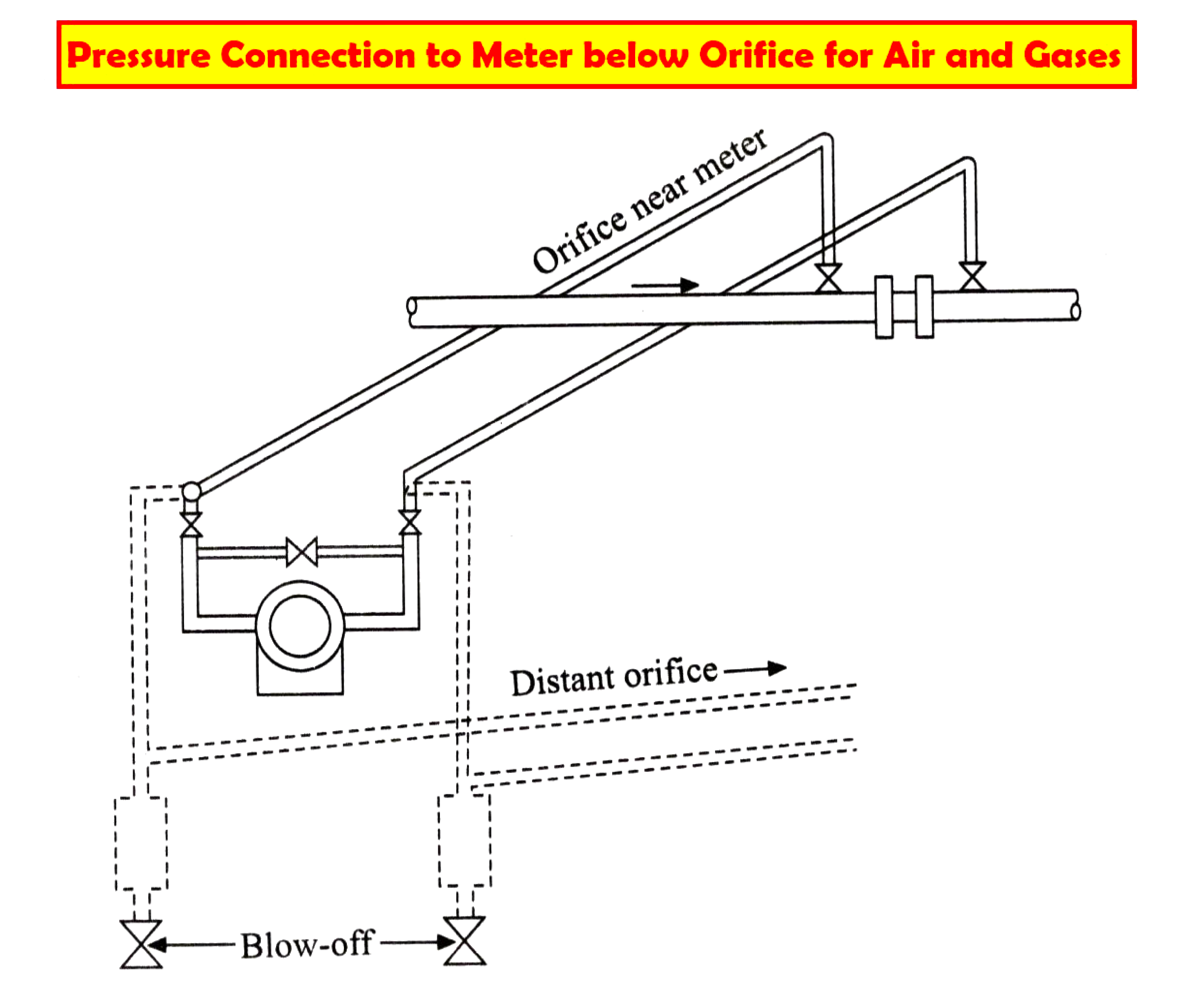
If the Differential Pressure Transmitters (DPT) are to be located above the level of the main pipeline with the orifice plate fixed. The pressure pipe should be laid as follows.
- The impulse pipe is continuously raised at a slope of nearly 1:10 from the orifice to the transmitter as shown in the Figure below.
- The pressure pipes must be fixed with blow-off drains to be drained at suitable intervals as shown in Figure B.
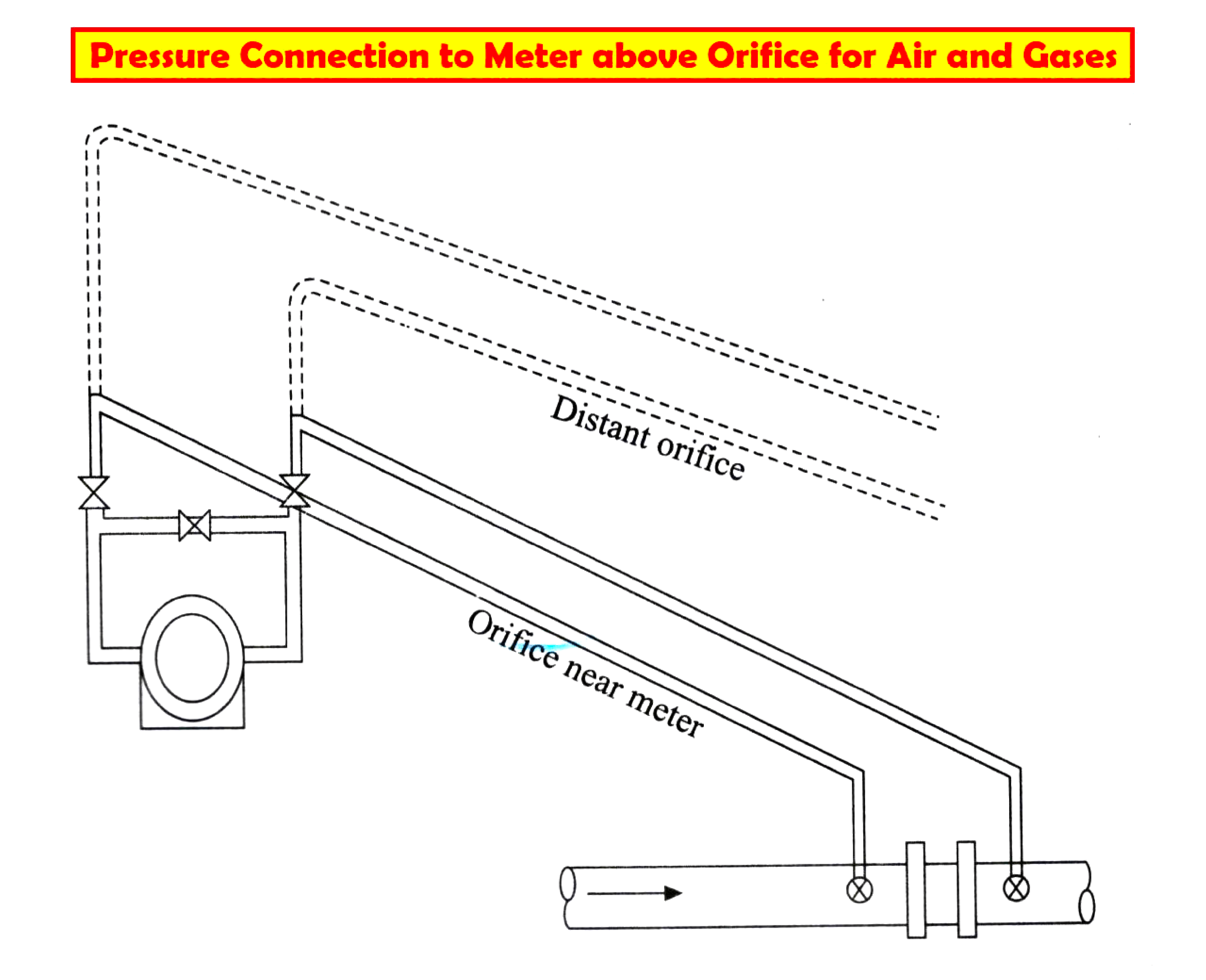
A dotted line in the Figure shows if the orifice is located at a distance away.
The pressure lines are lifted to avoid dust particles or water droplets flowing along with the medium in the main line that causes choking of the pressure lines. Because these pressure lines are smaller in ID compared to the main line.
The drain valve is also installed in the main line to drain dust particles or water droplets at regular intervals.
To drain the condensed water, dust, and mud collected inside the line the drain valves or blow-off valves are installed near the transmitter.
Measurement of Pressure
- Bourdon gauges measure the fuel oil and atomized steam pressure for local indication at the field.
- Strain gauge type or capacitance type electronic transmitters are used for transmission purposes.
- The temperature of the oil must be maintained by steam tracing outside the signal pipelines because the oil may get solidified in pressure pipes during pressure measurement.
Fuel Gas and Combustion Air Pressure
The pressure of fuel gas and combustion air lies between 0 to 2000 mm Wg.
Membrane type or capsule type sensors are used both for local indication and for transmission purposes.
The following are some of the sensing points.
- Main line pressure of Fuel gas
- Pressure before and after the pressure control valve
- FD fan outlet pressure
- Pressure before and after air preheater
- The pressure just before the burner
Flue Gas and Waste Gas Pressures
- The pressure of the flue gas from the combustion chamber to the chimney through ID varies between 50 to 100 mm Wg.
- The positive pressure is due to the combustion air pressure and gas pressure at the entering point.
- The ID fan and chimney generate negative pressure to flow the flue gas.
- Low pressures are measured by DP sensors using direct reading and transmission type diaphragm or membrane.
The various measuring locations are listed below:
- Combustion chamber pressure
- Pressure before and after the economizer
- Pressure before and after air preheater
- Pressure before and after ID fan
- Pressure before the chimney.
Furnace Draft
Basically,
- The air and fuel flow into the furnace or combustion chamber.
- Flue gas flows out from the combustion chamber to the atmosphere through the chimney.
- Furnace pressure is commonly referred to as draft pressure.
- The force driving this flow is the differential pressure between the gases inside and outside the furnace.
- The draft is maintained towards negative pressure to avoid ash and combustion products from being discharged from the furnace into surrounding areas through inspection ports, doors, feeders, etc.
- The furnace pressure must be around ± 20 mm Wg. The location of the furnace pressure tapping is very essential to get a truly representative sample.
- Pressure tap locations for measuring furnace draft are indicated in the figure below.
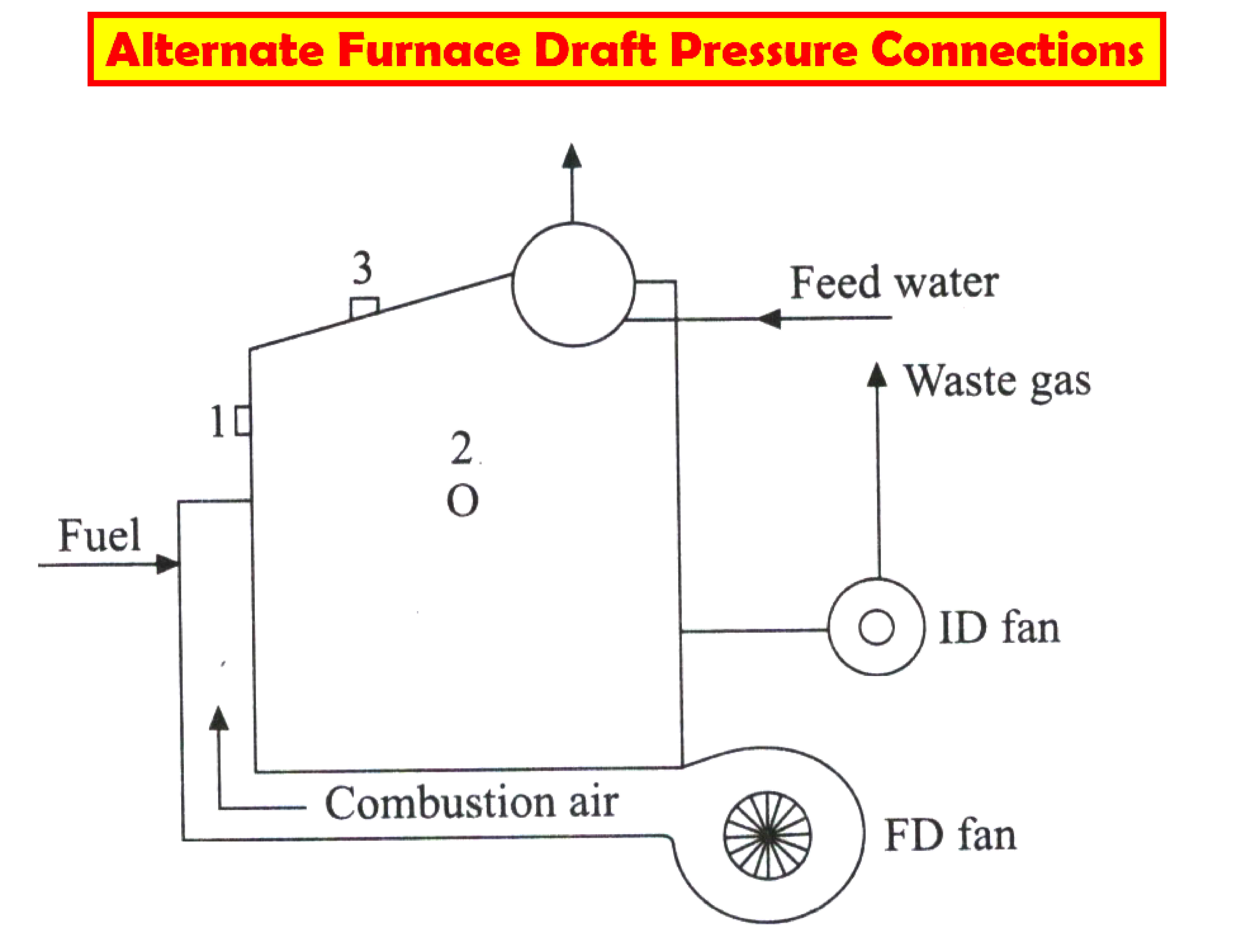
- The pressure connection on most boilers is located on the front (1), side (2), or roof (3) of the furnace as shown in figure C.
- The pressure measurement values differ due to the differing stack or chimney effects.
- For a particular boiler, the pressure measurements are for the same furnace chamber at these locations.
- The pressure measurement reads the highest value at the roof of the furnace; the value at the furnace roof becomes the controlling factor in determining the desired set point for the control of the set draft.
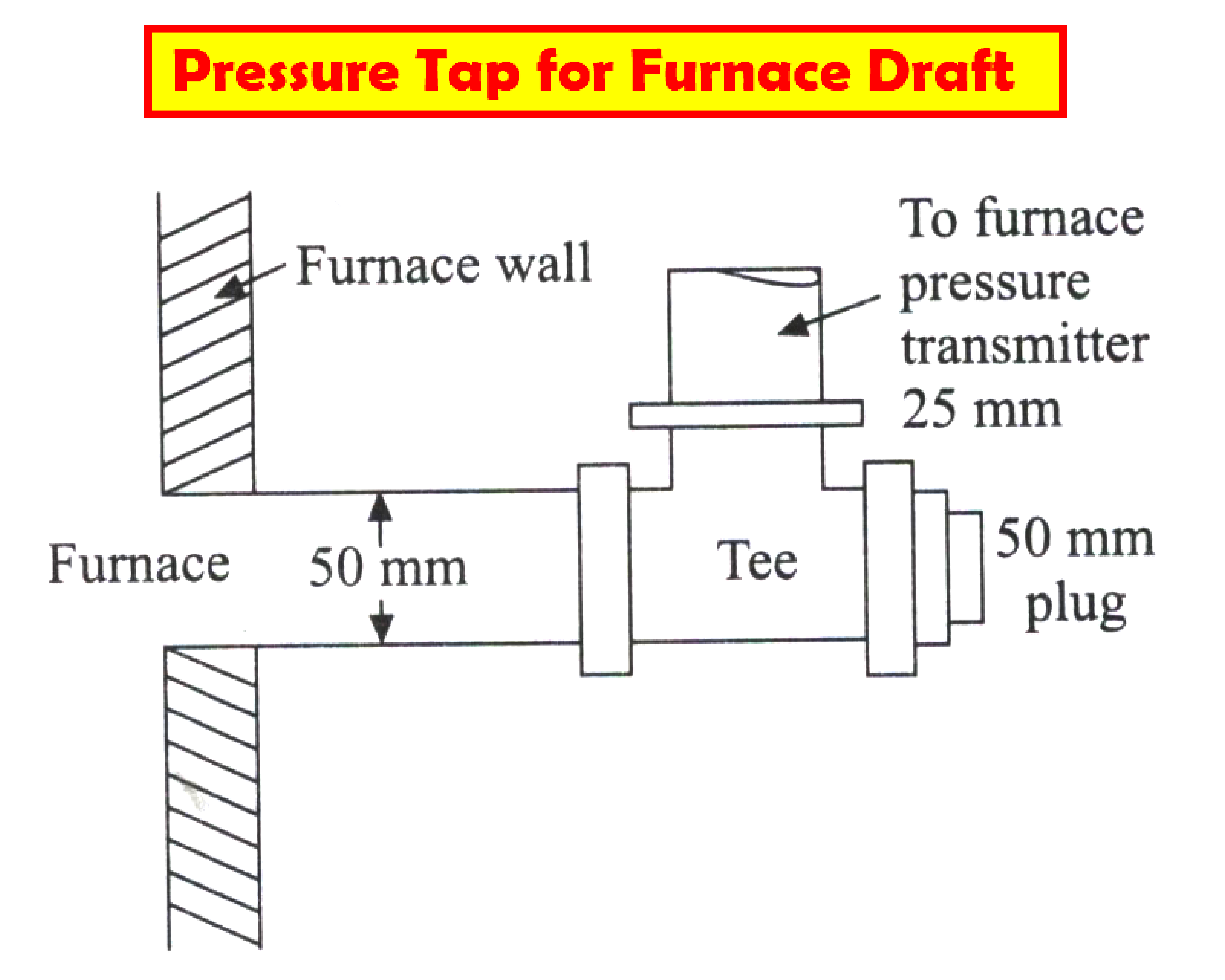
- Because of the very low pressure, The pressure connection should be large enough for slight changes in the furnace draft that can be very quickly felt by the measuring instrument.
- The pressure transmitter connections to the boiler furnace are made with a pipe of at least 25 mm diameter.
- The distance must be as minimum as possible for better results it should be less than 5 meters.
- A DP transmitter of about +20 mm Wg range is used for this measurement.
- A large diaphragm with one side vented to the atmosphere and the other side connected to the furnace is used to get better sensitivity.
A general arrangement is shown in the Figure below.
Gas Holder Level Measurement
The simplified arrangement is shown in the Figure below
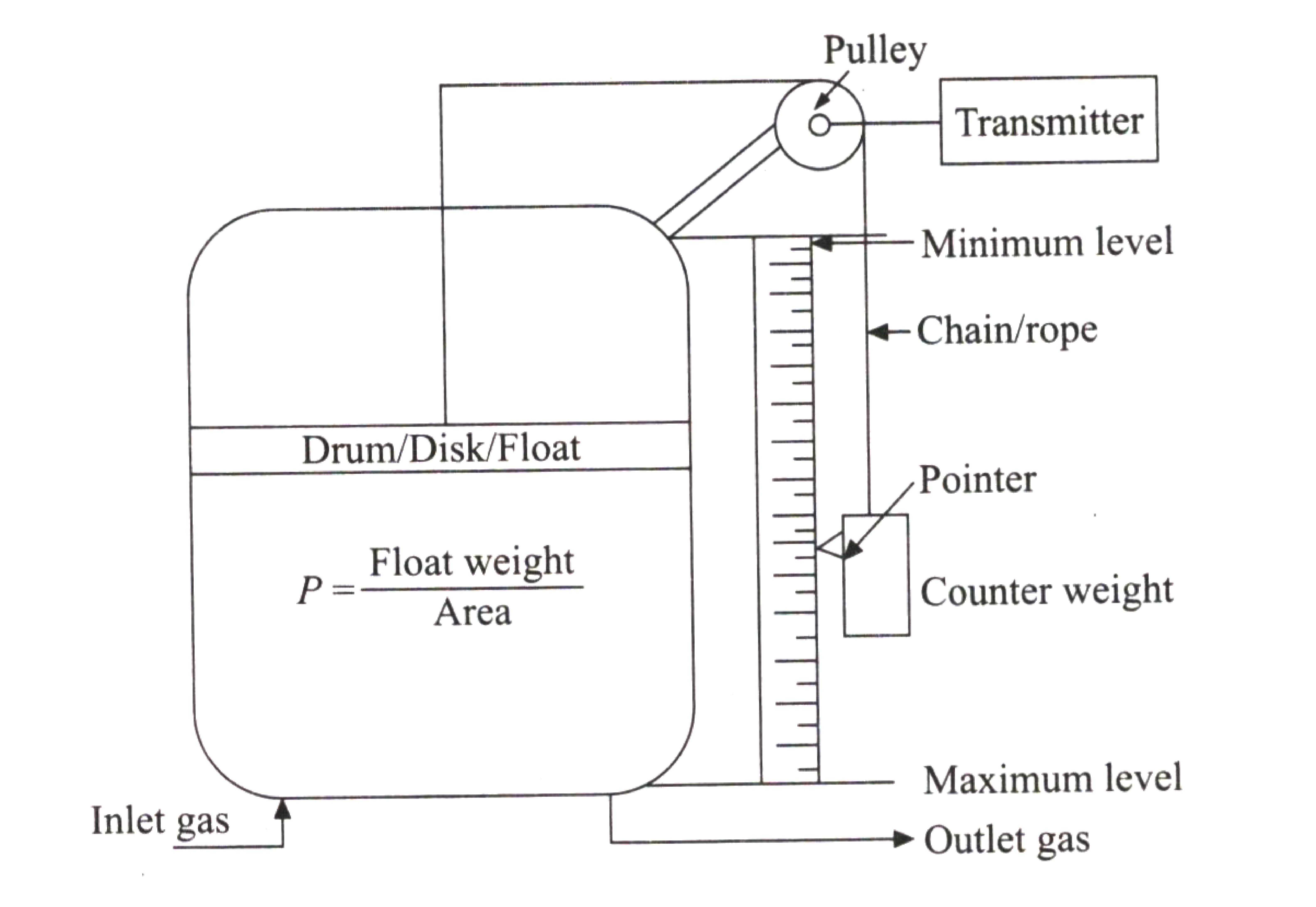
- The gas holder is intermediate equipment between the gas sources and the consuming unit.
- The gas fuel may be refinery gas or by-product gases or natural gas.
- The pressure of the fuel supplied in a pipeline must be maintained constant for proper and comfortable combustion control
- Fuel gas is first supplied to a gas holder whose drum or disk is designed to deliver the pressure as required.
- When maximum fuel gas is pumped to the gas holder, the pressure rises to lift the drum or disk in proportion to it.
- The drum position can be considered as the gas level inside the holder.
- For local indication, this position is measured using a chain and counter-weight arrangement connected to a large vertical dial. The dial reading will be in the reverse direction.
- For remote transmission and indication, the chain movement must be connected through the wheel and gear arrangement to a transmitter for transmitting the signal. The transmitter can convert the rotary motion into a standard electrical signal.
- The pointer is positioned at the top of the scale for the empty gas holder and vice versa.
- A small gearbox and a rotary transmitter will do the function. Synchros can be used instead of electronic transmitters in small power stations.
If you liked this article, then please subscribe to our YouTube Channel for Electrical, Electronics, Instrumentation, PLC, and SCADA video tutorials.
You can also follow us on Facebook and Twitter to receive daily updates.
Read Next:
- Turbine Bypass System
- Boiler Light-Up Sequence
- Deaerator Control System
- Turbine Speed Control system
- Boiler Feed Water System