A basic boiler system consists of various circuits such as
Contents
- Water & Steam Circuit
- Fuel & Ash Circuit
- Air & Flue Gas Circuit
- Cooling Water Circuit
Furnace Draft Control System
- Considering Air and Flue gas Circuit, here the Air and Fuel such as coal or Bagasse are mixed and ignited in the combustion chamber at the furnace.
- The driving force for this flow is the differential pressure between these gasses inside and outside the furnace. For the flow of Air and Fuel into the furnace and the flow of Flue gas from the furnace to the chimney.
- Furnace pressure is commonly known as draft or draft pressure or sometimes furnace draft.
- The combustion of fuel requires oxygen called air, to move the required air through the fuel bed and to produce a flow of the gaseous products of combustion out from the furnace, to the chimney through the superheater, economizer, and air preheater.
- This requires a pressure difference to accelerate the gasses to their final velocity plus friction losses.
- This pressure difference is known as draft whether measured above or below atmospheric pressure.
- Generally, this draft is maintained slightly negative to prevent the combustion products, and ash from being discharged from the furnace into surrounding areas through inspection ports, doors, feeders, etc.
- Also, this should be as close to the atmosphere to minimize the ingestion of excess air drawn through openings.
- Normally in a boiler, a forced draft (FD) fan draws air from the atmosphere and gives a huge boost to the draft.
- In addition solid, liquid, and gaseous fuel adds extra pressure inside the combustion chamber.
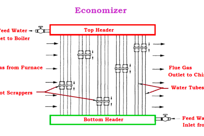
- After the combustion, the flue gasses travel toward the atmosphere through the economizer, air preheater, and chimney which are normally pressure-reducing components.
- Finally, when the chimney is not in a position to develop enough natural draft to accept flue gas, the induced draft (ID) fan is added to serve the purpose.
- These Fans and chimneys produce pressure in the positive direction.
- Furnaces are classified by the method for moving air and other gasses through the system.
Natural Draft (ND)
- Natural draft operates below atmospheric pressure.
- A natural draft furnace uses the stack (chimney) effect.
- Gasses inside the chimney are less dense than outside the chimney.
- The gasses in the stack will rise, creating a vacuum (suction) that will draw the combustion gasses or flue gas out of the furnace.
- The draft that will be produced by a stack is a function of the height of the stack and the flue gas temperature.
- Natural draft is used to supplement the mechanical draft produced by fans.
Forced Draft (FD)
- A forced draft furnace uses an FD fan or blower to force combustion air through the system by sucking air from the atmosphere.
- This control is accomplished by regulating the fan speed and the position of the corresponding damper.
- This type of furnace is operated slightly above atmospheric pressure.
Induced Draft (ID)
- This Induced Draft fan at the boiler end takes its suction from the boiler flue gas stream and discharges this flue gas to the chimney is called an induced draft fan.
- This Fan receives flue gas through the furnace and the combustion air into the furnace.
- An Induced Draft fan makes high stacks unnecessary.
- Control is accomplished by regulating the fan speed or damper operation.
- An induced draft furnace is operated slightly below atmospheric pressure.
Balanced Draft (BD)
- Furnaces equipped with both FD Fan and ID fan are known as a Balanced Draft system.
- To control furnace pressure, it is required to maintain a balance between the flow in and flow out of the furnace.
- The balanced draft furnace operates at negative pressures to avoid leakage of flue gas into the surroundings.
- However, too low pressure must also be avoided to reduce air leakage into the furnace and to prevent furnace implosion in extreme cases.
- FD fan damper is generally manipulated by the airflow controller.
- The fan damper is manipulated by the furnace pressure controller.
F.D. Fan Control (Forced Draft Control)
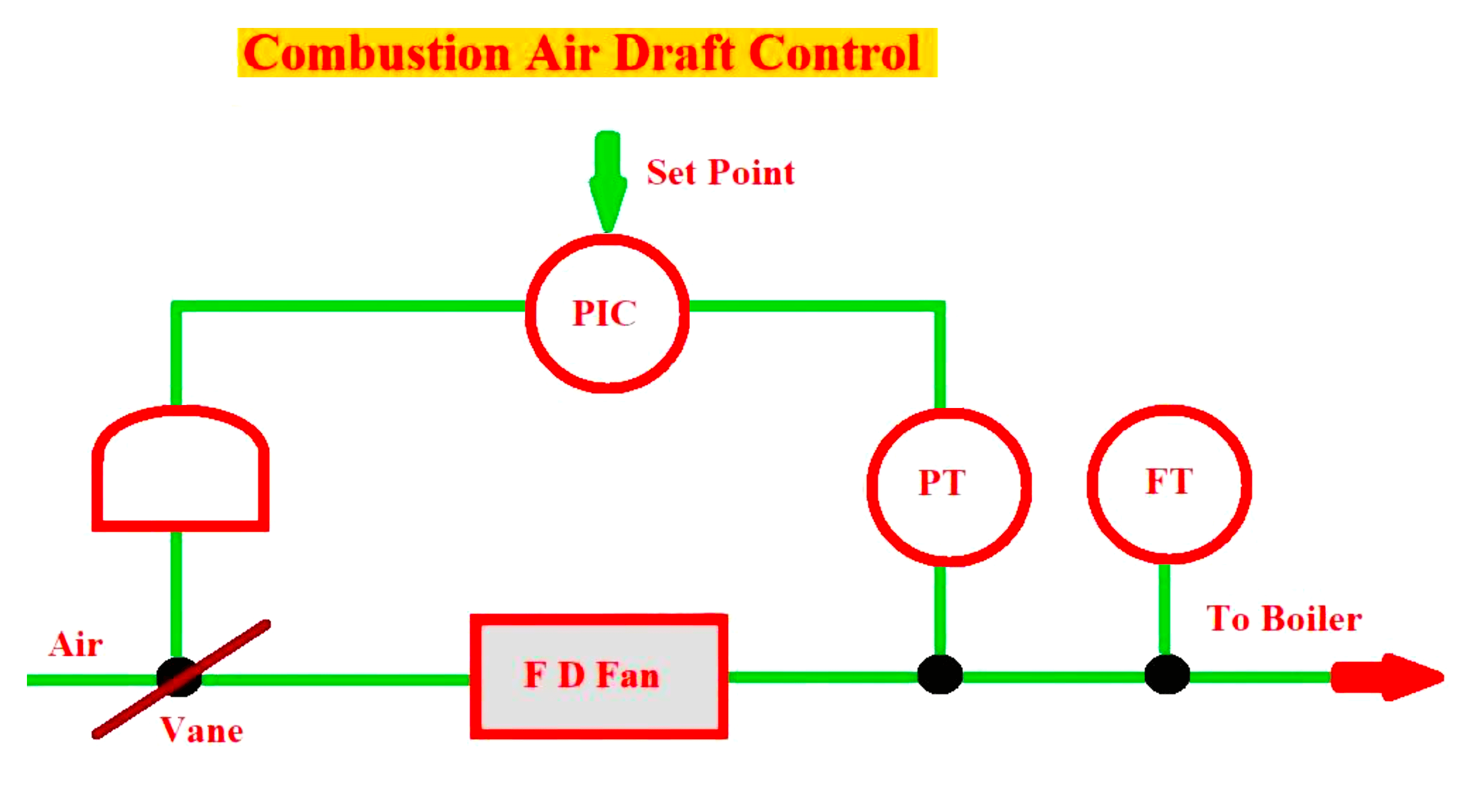
- A simplified schematic diagram of Combustion air Draft Control is shown above
- In all thermal power plants, with a number of boilers in operation, a master controller will decide the load sharing among boilers and hence the fuel rate. Depending on the fuel rate of a particular boiler, the air requirement and hence the draft to be developed by the FD fan is decided.
- FD fan controls are done according to the boiler.
- FD fan along with its inlet vane control arrangement is engaged for the control of combustion air.
- It is done by considering either the furnace inlet air pressure or total airflow.
- The airflow signal is maintained by keeping constant air pressure or air pressure signal as input to the controller.
- The controller output controls the inlet vanes of the FD fan to achieve the result.
- Instead of controlling the inlet vane or damper, it is possible to control the fan speed but it is very expensive.
- This control takes care of the total air required for the boiler as per demand by the master controller.
- The draft thus generated is called forced draft which takes care of losses caused in air duct and preheater, and in fuel bed resistances.
I.D. Fan Control (Induced Draft Control)
A schematic diagram of a furnace draft or induced draft control is shown in the figure below
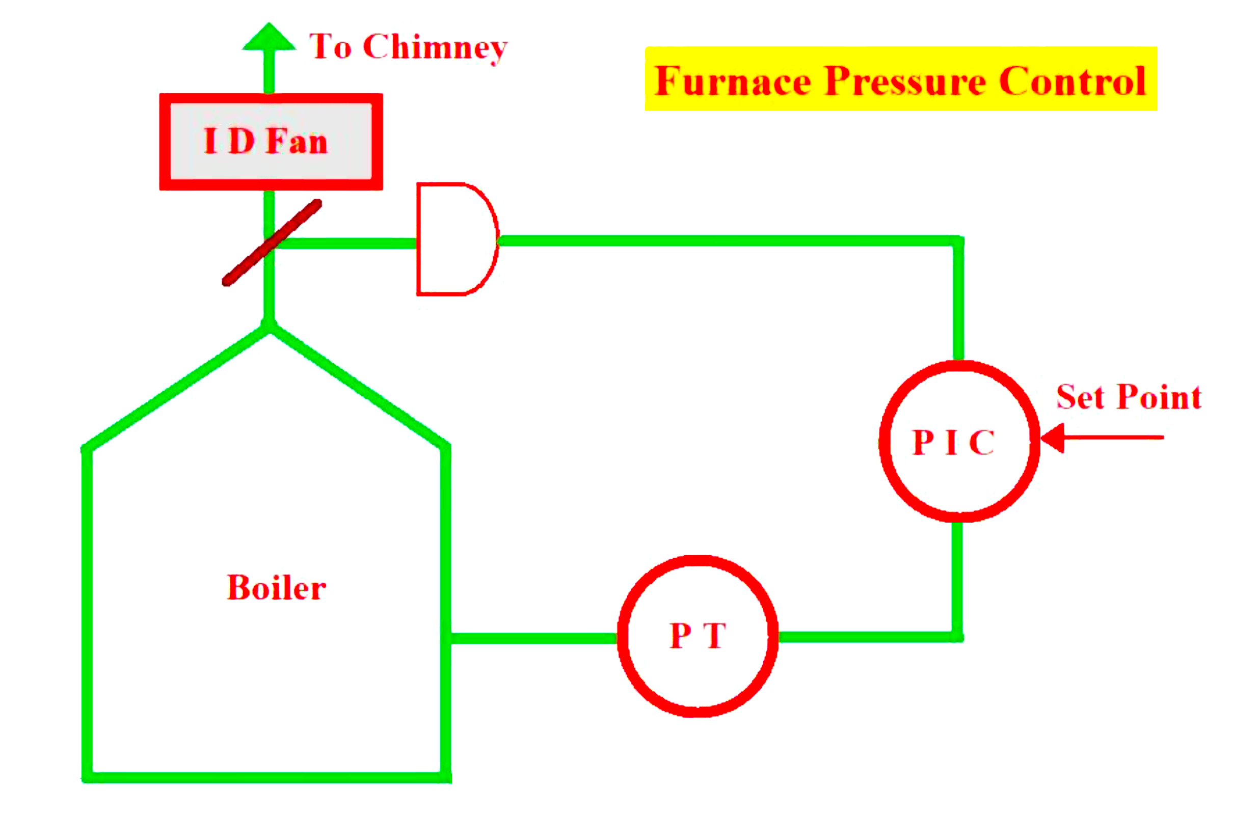
- The purpose of this Induced Draft control is to maintain the pressure of the furnace or combustion chamber at a slightly negative value.
- This is achieved by an induced draft fan with damper control.
- The range of the pressure transmitters must be around ±20 mmwc.
- The measurement of the furnace draft produces a noisy signal, limiting the loop gain to relatively low values.
- In some cases, it is necessary to use only integral control to stabilize the loop. Additionally, this stability and interaction problems may arise in systems due to measurement lags.
Balanced Draft Control
The below figure shows a system where both FD fan loop
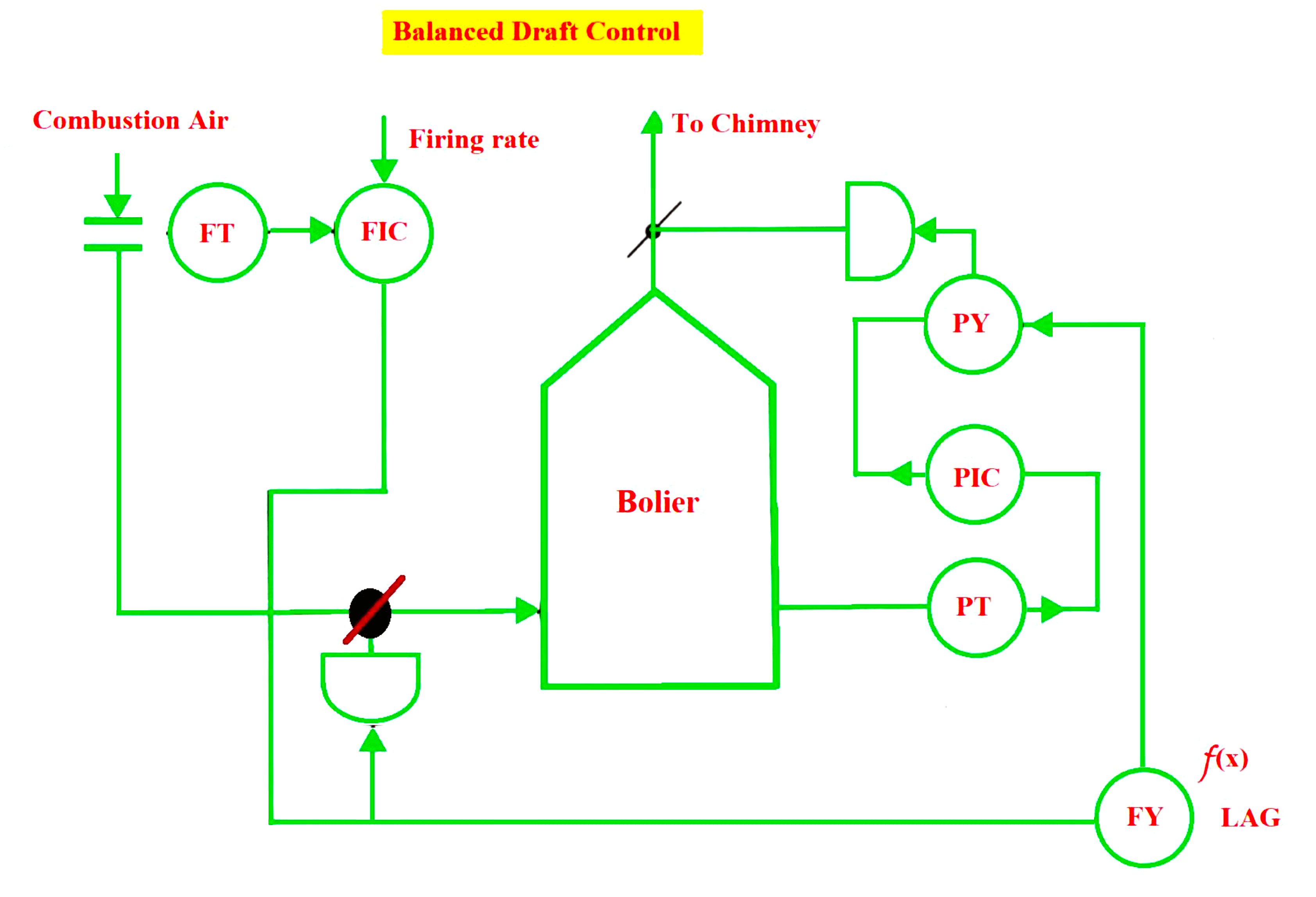
- This balanced draft control is generally employed only in large boilers.
- In this case, Both the FD fan and the ID fans are operated simultaneously.
- FD fan generates positive pressure during the start of the flow path.
- The ID fan creates suction pressure at the end of the flow path.
- The pressure will be the same as atmospheric pressure at some point in the path.
- It is designed so that the pressure in a combustion chamber must be slightly negative so that there is either hot gas leakage or excessive cold air infiltration.
- This is achieved by maintaining the pressure at the top of the furnace slightly negative.
- In a balanced draft system, this FD fan loop is used to satisfy the net airflow requirement and the ID fan loop is used for controlling the furnace draft.
- There is always a possibility of interaction between these two FD fan loops and ID fan loops.
- Some suitable designs are to be made to reduce the interaction occurring between them.
- The airflow controller moves the FD fan damper directly and the ID fan damper with a time lag.
- The airflow controller sends a signal to the furnace draft controller which is considered to be the feed-forward signal.
- Hence whenever the airflow to the furnace is changed, the outflow from the furnace will also start changing with a dynamic compensation lag.
- This mismatch is finally corrected by the furnace pressure controller to trim the feed-forward signal at PY.
If you liked this article, then please subscribe to our YouTube Channel for Electrical, Electronics, Instrumentation, PLC, and SCADA video tutorials.
You can also follow us on Facebook and Twitter to receive daily updates.
Read Next:
- Turbine Bypass System
- Boiler Light-Up Sequence
- Deaerator Control System
- Turbine Speed Control system
- Boiler Feed Water System


The ID fan damper is manipulated by the furnace pressure controller. Please add ID