Inst ToolsInst ToolsInst Tools
  • Courses
  • Automation
    • PLC
    • Control System
    • Safety System
    • Communication
    • Fire & Gas System
  • Instrumentation
    • Design
    • Pressure
    • Temperature
    • Flow
    • Level
    • Vibration
    • Analyzer
    • Control Valve
    • Switch
    • Calibration
    • Erection & Commissioning
  • Interview
    • Instrumentation
    • Electrical
    • Electronics
    • Practical
  • Q&A
    • Instrumentation
    • Control System
    • Electrical
    • Electronics
    • Analog Electronics
    • Digital Electronics
    • Power Electronics
    • Microprocessor
  • Request
Search
  • Books
  • Software
  • Projects
  • Process
  • Tools
  • Basics
  • Formula
  • Power Plant
  • Root Cause Analysis
  • Electrical Basics
  • Animation
  • Standards
  • 4-20 mA Course
  • Siemens PLC Course
Reading: What is Megger Test?
Share
Font ResizerAa
Inst ToolsInst Tools
Font ResizerAa
  • Courses
  • Design
  • PLC
  • Interview
  • Control System
Search
  • Courses
  • Automation
    • PLC
    • Control System
    • Safety System
    • Communication
    • Fire & Gas System
  • Instrumentation
    • Design
    • Pressure
    • Temperature
    • Flow
    • Level
    • Vibration
    • Analyzer
    • Control Valve
    • Switch
    • Calibration
    • Erection & Commissioning
  • Interview
    • Instrumentation
    • Electrical
    • Electronics
    • Practical
  • Q&A
    • Instrumentation
    • Control System
    • Electrical
    • Electronics
    • Analog Electronics
    • Digital Electronics
    • Power Electronics
    • Microprocessor
  • Request
Follow US
All rights reserved. Reproduction in whole or in part without written permission is prohibited.
Inst Tools > Blog > Electrical Basics > What is Megger Test?

What is Megger Test?

A Megger test is done by an insulation tester resistance meter to verify the electrical insulation of a wire.

Last updated: September 28, 2022 4:13 pm
Viral Nagda
Electrical Basics
1 Comment
Share
5 Min Read
SHARE

In this post, we will see the concept of the Megger Test in electrical engineering.

An electrical wire consists of a conductor and insulator. Basically, if you see a wire, the internal metal strap is the conductor and the outer rubber coating covering the conductor is the insulation. It is because of this insulation that we are able to touch a live wire (not the metal strap).

Insulation is a measure of resistance. The higher the resistance, the higher the insulation provided. Over a course of time, due to outside weather, rust and dust, etc. the rubber coating insulator starts to fade or cut away.

If the insulator is cut in a large amount and a large amount of conductor is exposed, then there are chances of spark or a major accident. This is because wires always run in a bunch of pairs, and any conductor short link with another conductor can create a spark or fire due to a short circuit.

So, it is important to check the insulation of a wire. This test is done by the Megger test. A Megger test is done by an insulation tester resistance meter to verify the electrical insulation of a wire.

Megger Test

Construction of Megger

A Megger meter is also called a Mega-ohm meter. This is because the unit of the meter is in Mega-Ohms. From a small wire used at home to large wires used in transformers, the resistance is checked by the Megger test.

Apart from resistance checking, it is also used to check the open circuit and short circuit of motor windings and electrical wires.

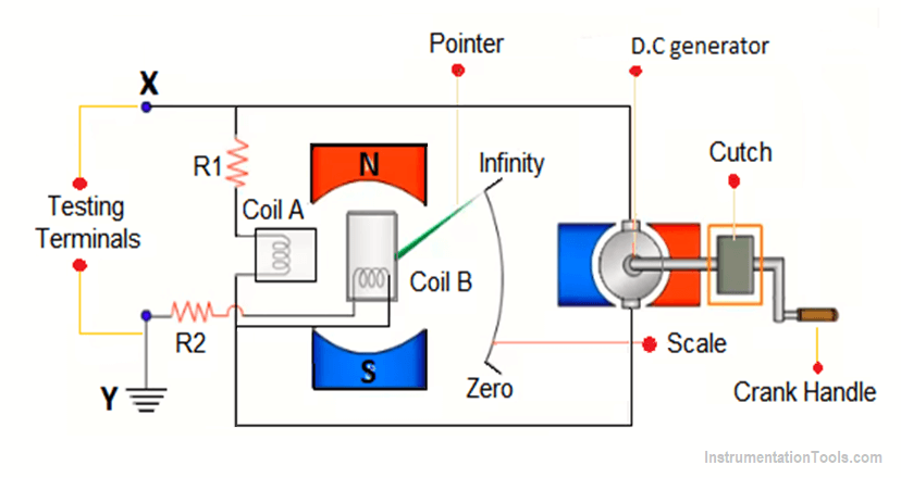
The meter comes in two types – electronic and manual. So, what is the difference between the two? Well, let us first understand how the meter works. The meter is an internal DC voltage producer.

The output DC voltage is given to the wires to be checked. When the voltage passes through them, the meter checks the resistance of the wires connected.

So, basically, an electronic meter is the one that has a battery and the voltage is produced automatically by pressing a test button. A manual meter is one that has a hand lever and the lever needs to be rotated to produce the voltage.

It is not guaranteed for sure that you will get the exact area of the problem or the exact amount of resistance leakage, but you get a very approximate value of the resistance of the wires.

Suppose you are conducting a Megger test of a transformer wire set. For that, you first need to disconnect the supply voltage given to the transformer (HV and LV). Then, the meter is connected between these two wires and you get the resistance value between the phase supply wires. Then the meter is connected between HV and earth point; and then LV and earth point to get the resistance value between phase and ground. This verifies the electrical insulation fully with respect to any potential.

The voltage levels depend on the equipment or wire you are testing. The higher the equipment or wire rating, the higher will be the voltage applied. This fool-proofs the insulation information of the wire and assures the user regarding that.

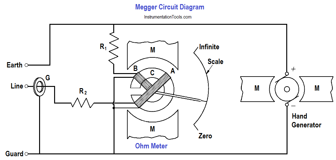
A current limiting resistor is connected in series to protect damage in case of low resistance of the circuit. A very good resistance value means a large value of Ohms or infinite value. A bad resistance value means a small amount of Ohms.

Megger Circuit Diagram

Many safety precautions need to be followed when doing this test; just due to a large amount of voltage applied. The first and utmost importance is that you should not touch the leads or wires in any case when it is tested. Before doing this test, de-energize or discharge the circuit completely.

Megger test is a very old method of checking insulation. Nowadays, many new modern techniques have come. But this measure is tried and tested, and always gives very good results.

If you liked this article, then please subscribe to our YouTube Channel for Instrumentation, Electrical, PLC, and SCADA video tutorials.

You can also follow us on Facebook and Twitter to receive daily updates.

Read Next:

  • What is Electrical Busbar?
  • Motor Control Center
  • What is Electrical Slip Ring?
  • High-Speed Counters in PLC
  • Searching Tag number in PLC
Don't Miss Our Updates
Be the first to get exclusive content straight to your email.
We promise not to spam you. You can unsubscribe at any time.
Invalid email address
You've successfully subscribed !

Continue Reading

Safety Tips When Working With Electricity
What is Floating Neutral? – Electrical Engineering Basics
Electrical Terminology
Star Delta Starter – Working, Circuit, Advantages, Disadvantages
Advantages of Three Phase System Compared to Single Phase System
Electrical Components Overheating – Causes, Troubles, Prevent
Share This Article
Facebook Whatsapp Whatsapp LinkedIn Copy Link
Share
1 Comment
  • JAMES NKETIAH PIESIE says:
    October 20, 2021 at 12:56 pm

    Thank you Very much,this piesce have nice infotmation.

    Reply

Leave a Reply Cancel reply

Your email address will not be published. Required fields are marked *

Stay Connected

128.3kFollowersLike
69.1kFollowersFollow
210kSubscribersSubscribe
38kFollowersFollow

Categories

Explore More

Difference Between Open Circuit and Close Circuit
Difference between RCCB and RCBO
Difference Between Alternator and Generator?
Bus Riser in Switchgear
Difference Between Circuit Breaker and Fuse
Basics of Electricity Rates
Worldwide Voltage & Frequency Values
Electric Stress Control in Cables, Joints, and Terminations

Keep Learning

Wiring Diagram Forward-Reverse for 3 Phase Motor

Motor Forward and Reverse Direction Control using Limit Switches

Working Principle of Overload Relay

Working Principle of Overload Relay

Motor Disconnector Switch

What is a Motor Disconnector Switch? – Purpose, Principle, Factors

Motor Controls

Design and Implement Motor Control – Electrical Engineering

What is an HRC Fuse

What is an HRC Fuse? – Material, Types, Advantages

Motor Control Center Purpose

Motor Control Center – Purpose, Classification, and Advantages

What is an ELV System - Extra Low Voltage

What is an ELV System? – Extra Low Voltage

Earthing Calculations

Electrical Earthing Calculations

Learn More

Electrical Motors Interview Question And Answers

Electrical Motors Interview Question And Answers

Pull Cord Switch Principle

Pull Cord Switch Working Principle

Modbus Function code 02 – Read Contact(s)

Modbus Function Command Formats

Free Schneider PLC Training - Automation Course

Free Schneider PLC Training – Automation Course

Calculate Power in Series RCL Circuit

Calculate Power in Series RCL Circuit

Digital Instrument Example

Digital Measuring Instruments – Types, Functions, Advantages, Disadvantages

Level Transmitters Auto Calibration

DP Level Transmitter Auto Calibration

Typical Purging Installation

Purging of Instruments

Menu

  • About
  • Privacy Policy
  • Copyright

Quick Links

  • Learn PLC
  • Helping Hand
  • Part Time Job

YouTube Subscribe

Follow US
All rights reserved. Reproduction in whole or in part without written permission is prohibited.
Welcome Back!

Sign in to your account

Username or Email Address
Password

Lost your password?