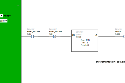
Write a PLC program that if you pressed the push button (PB) for the first time then the motor should run in a clockwise (CW) direction and if pressed again it runs in counter-clockwise (CCW) direction and so on until the stop PB is pressed.
Note the best practice to learn the PLC programming is to start writing the PLC program, take your time before you review the answer.
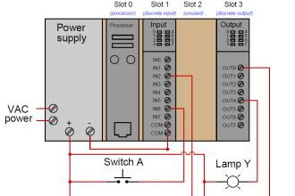
Inputs & outputs:
I0.0: Push Button (Normally open contact)
I0.1: Stop Push Button (Normally Closed Contact)
Q0.0: Motor_CW direction
Q0.1: Motor_CCW direction
M0.0: marker_01 for positive edge.
M0.1: marker_02 for negative edge.
M0.2: marker_03 for negative edge.
M0.3: marker_04 for negative edge.
CW and CCW Operation of Motor from Same Push button
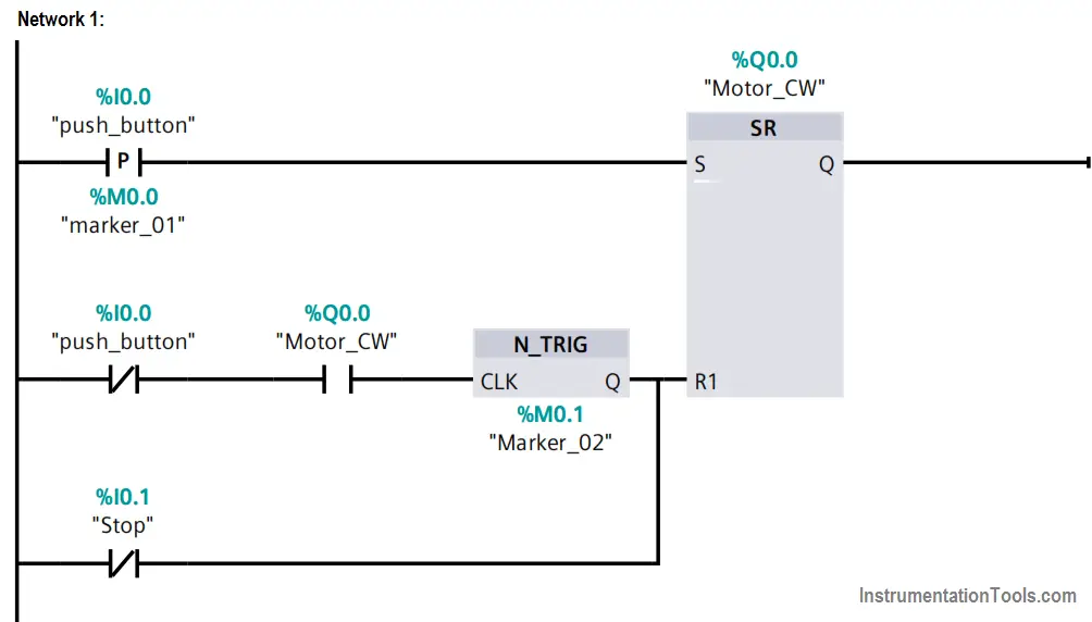
PLC Logic Explanation
When the push_button is pressed for the first time, the set bit in the Motor_CW SR flip flop is energized by a positive_trigger(to ensure it is energized for one scan cycle).
When the push_button is released the motor_CW flip flop is still on.
When the push_button is pressed for the second time the reset bit in the motor_CW is energized as it is the negative trigger of the Push_button normally closed bit and the normally open of motor_CW bit.
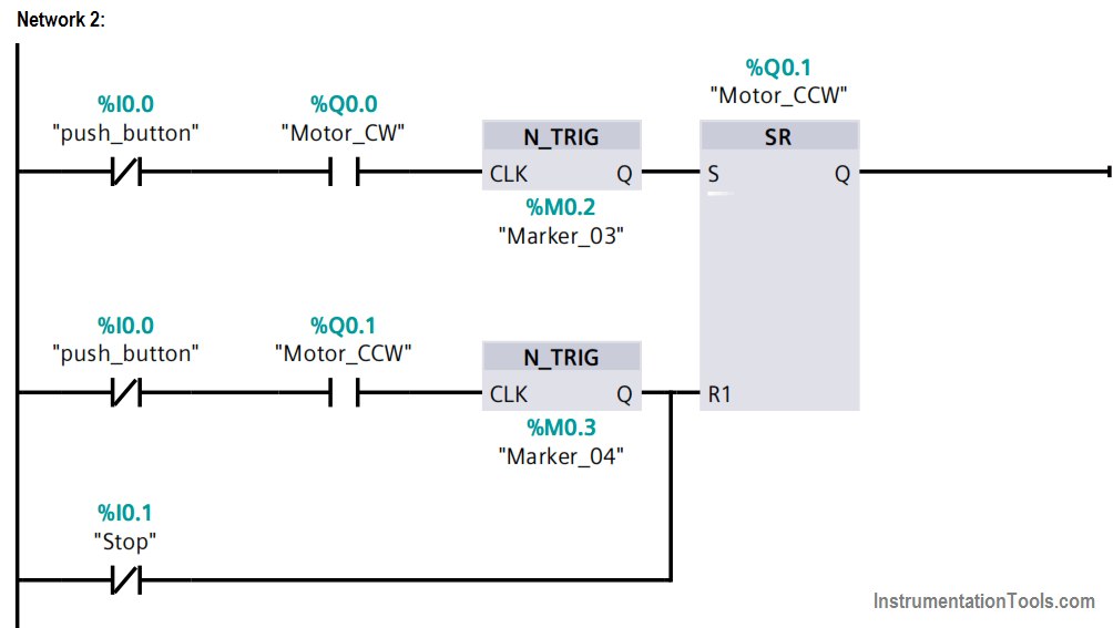
Then the set bit in Motor_CCW SR flip flop is energized as it is the negative trigger of the normally closed bit of push_button and the motor_CW.
When the Push_button is released the motor_CCW is still on.
When the push_button is pressed again the reset bit in the motor_CCW is energized and the set bit in the motor_CW is energized and so on.
If the stop push button is pressed any time the motor would stop.
Author: Karim Ali Anwar
If you liked this article, then please subscribe to our YouTube Channel for PLC and SCADA video tutorials.
You can also follow us on Facebook and Twitter to receive daily updates.
Read Next: