Inst ToolsInst ToolsInst Tools
  • Courses
  • Automation
    • PLC
    • Control System
    • Safety System
    • Communication
    • Fire & Gas System
  • Instrumentation
    • Design
    • Pressure
    • Temperature
    • Flow
    • Level
    • Vibration
    • Analyzer
    • Control Valve
    • Switch
    • Calibration
    • Erection & Commissioning
  • Interview
    • Instrumentation
    • Electrical
    • Electronics
    • Practical
  • Q&A
    • Instrumentation
    • Control System
    • Electrical
    • Electronics
    • Analog Electronics
    • Digital Electronics
    • Power Electronics
    • Microprocessor
  • Request
Search
  • Books
  • Software
  • Projects
  • Process
  • Tools
  • Basics
  • Formula
  • Power Plant
  • Root Cause Analysis
  • Electrical Basics
  • Animation
  • Standards
  • 4-20 mA Course
  • Siemens PLC Course
Reading: Electric Circuit : Open & Short Circuits
Share
Font ResizerAa
Inst ToolsInst Tools
Font ResizerAa
  • Courses
  • Design
  • PLC
  • Interview
  • Control System
Search
  • Courses
  • Automation
    • PLC
    • Control System
    • Safety System
    • Communication
    • Fire & Gas System
  • Instrumentation
    • Design
    • Pressure
    • Temperature
    • Flow
    • Level
    • Vibration
    • Analyzer
    • Control Valve
    • Switch
    • Calibration
    • Erection & Commissioning
  • Interview
    • Instrumentation
    • Electrical
    • Electronics
    • Practical
  • Q&A
    • Instrumentation
    • Control System
    • Electrical
    • Electronics
    • Analog Electronics
    • Digital Electronics
    • Power Electronics
    • Microprocessor
  • Request
Follow US
All rights reserved. Reproduction in whole or in part without written permission is prohibited.
Inst Tools > Blog > Electrical Theory > Electric Circuit : Open & Short Circuits

Electric Circuit : Open & Short Circuits

Last updated: August 9, 2019 7:35 pm
Editorial Staff
Electrical Theory
No Comments
Share
1 Min Read
SHARE

Each electrical circuit has at least four basic parts:

  1. a source of electromotive force,
  2. conductors,
  3. load or loads, and
  4. some means of control.

In Figure 13, the source of EMF is the battery; the conductors are wires which connect the various component parts; the resistor is the load; and a switch is used as the circuit control device.

Electric Closed Circuit

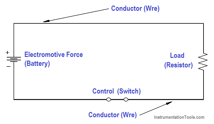
Figure 13 Closed Circuit

A closed circuit (Figure 13) is an uninterrupted, or unbroken, path for current from the source (EMF), through the load, and back to the source.

An open circuit, or incomplete circuit, (Figure 14) exists if a break in the circuit occurs; this prevents a complete path for current flow.

Electric Open Circuit

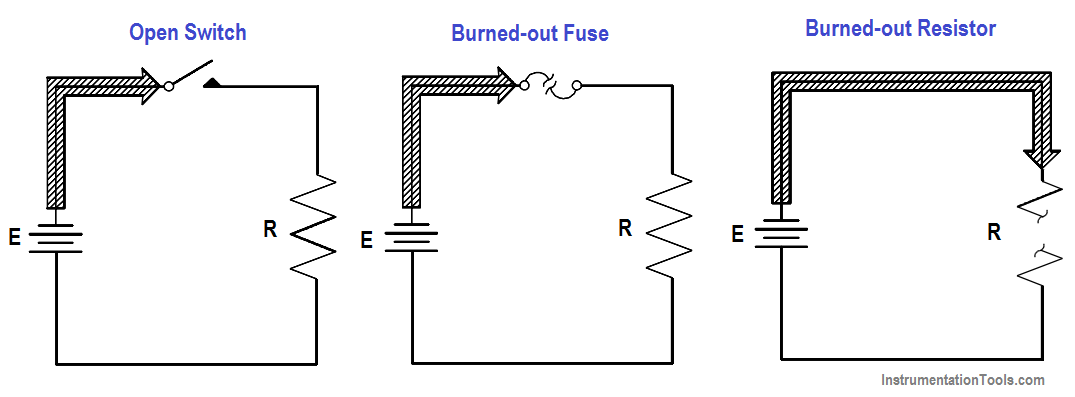
Figure 14 Open Circuit

A short circuit is a circuit which offers very little resistance to current flow and can cause dangerously high current flow through a circuit (Figure 15).

Short circuits are usually caused by an inadvertent connection between two points in a circuit which offers little or no resistance to current flow.

Shorting resistor R in Figure 15 will probably cause the fuse to blow.

Electric Short Circuit

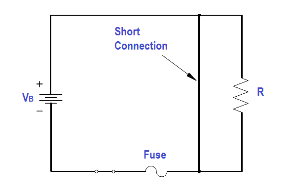
Figure 15 Short Circuit

Don't Miss Our Updates
Be the first to get exclusive content straight to your email.
We promise not to spam you. You can unsubscribe at any time.
Invalid email address
You've successfully subscribed !

Continue Reading

Series – Parallel Circuit Analysis
Ohm Meter
Generator Action in a Motor
D’Arsonval Meter Movement
Block Diagram
Reading Electrical Schematics
Share This Article
Facebook Whatsapp Whatsapp LinkedIn Copy Link
Share
Leave a Comment

Leave a Reply Cancel reply

Your email address will not be published. Required fields are marked *

Stay Connected

128.3kFollowersLike
69.1kFollowersFollow
210kSubscribersSubscribe
38kFollowersFollow

Categories

Explore More

DC Motor Speed
Series-Wound DC Generators
DC Machines Construction
Starting a Synchronous Motor
Impedance in RLC Circuits
DC Circuit Analysis Node Equations
Power in Balanced 3 Phase Loads
Voltage and Current Phase Relationships in an Inductive Circuit

Keep Learning

Core-Type Transformer

Transformer Turns Ratio

Measuring Circuit Voltage

Voltmeters

4-Wire, Three-Phase Delta Wiring System

4-Wire, Three-Phase Delta Wiring System

LVR Motor Controller Operation

Low Voltage Protection (LVP) and Low Voltage Release (LVR)

Transformer Efficiency

Transformer Efficiency

Induced EMF

Magnetic Circuits

relationship between resistance, reactance, and impedance

Impedance

AC generator Voltage Regulators

AC Generator Voltage Regulators

Learn More

Caliper Calibration

Setting Up for Success: Preparing for Caliper Calibration

Top 300 Digital Signal Processing Projects (DSP)

Top 300 Digital Signal Processing Projects – DSP Project Ideas

Data Types in PLC

Data Types in PLC – Bit, Byte, Integer, Real, String

Mass Spectrometer Questions and Answers

Quadrupole Mass Spectrometer

PLC based Automatic Bell System

PLC based Automatic Bell System for a School

Steam Letdown Station Problems

Steam Letdown Station Problems and their Solutions

Automatic Bottle Filling System using PLC

Automatic Bottle Filling System using PLC

How Twisted Wire Cables Eliminates Noise Voltage

Inductive Coupling Effects

Menu

  • About
  • Privacy Policy
  • Copyright

Quick Links

  • Learn PLC
  • Helping Hand
  • Part Time Job

YouTube Subscribe

Follow US
All rights reserved. Reproduction in whole or in part without written permission is prohibited.
Welcome Back!

Sign in to your account

Username or Email Address
Password

Lost your password?