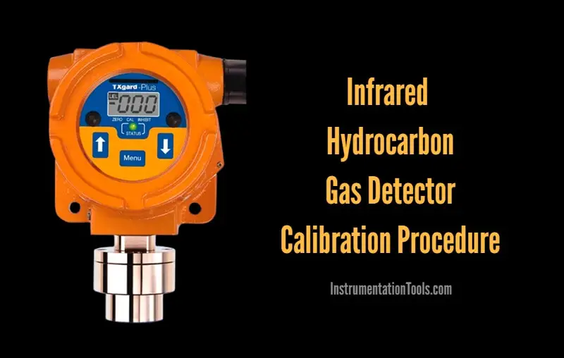
Study about the Infrared Hydrocarbon (HC) Gas Detector Calibration Procedure with zero and span gas testing.
Contents
Hydrocarbon Gas Detector Calibration
Before starting the job, take the proper work permit and inform to all the respective departments. Also do force the respective logics or interlocks if any.
The below calibration procedure explained for crowcon make HC gas detectors.
Zero Calibration
- Open the Infrared Hydrocarbon Gas Detector’s cover cap by rotating it anticlockwise.
- Check the Display which is located above on gas detector this display’s digits to be shown on clean atmospheric condition is “000 % LEL”.
- Check the +24 Volts DC Supply between + and – terminal of the Gas Detector.
- Check the Zero reading of the Gas Detector on test points on TP1 and TP2, it should be 40 mV / 4 mA.
- If it is not showing 40 mV correctly then adjust it by trim pot screw driver on to the by adjusting Zero trim Pot .
- Now the Zero calibration is completed.
Span Calibration
- For Span calibration of Gas Detector we required methane 50 % LEL + Balance Air Gas Cylinder, Calibration Cap, Fixed 0.5 Liter per Minute flow adjusting Pressure Regulator, calibration pipe and Cylinder valve opening key.
- Before going to calibrate the Gas Detector be sure that the Gas Detector is Zeroed by watching the display digit on display “000” and checking the mV on Gas Detector Test Points between TP1 and TP2 it should be 40 mV.
- Now the Gas Detector is ready for Span Calibration.
- Fix the Gas Detector calibration cap on to the Gas sensor.
- Fix the Gas calibration pipe’s first end to the Gas Calibration Cap.
- Take 50 % LEL Methane + Balance Air Gas Cylinder near to the Gas Detector.
- Fix 0.5 Liter per Minute constant flow Pressure Regulator to the Gas Cylinder.
- Fix the Gas calibration pipe’s second end to the Pressure Regulator’s nozzle.
- Open the gas Cylinder Valve by Cylinder Opening Key by rotating anticlockwise.
- Open the Pressure regulator knob slowly.
- Apply the calibration gas to the Gas Detector.
- See the Gas Detectors Display digit is increased from 000 to 50 and simultaneously Gas Detectors mV changing from 40 mV to 120 mV for 50 % LEL Gas.
- If gas Detectors reading is not reached up to 50 % LEL then adjust the Span value by adjusting the Cal pot.
- Now the Gas Detector mV showing on Digital Multi meter is 120 mV for 50 % LEL gas and Display digit showing “50” % LEL on Display board.
- The Span Calibration is completed.
Returning to Normal Operation
- Close the Gas Cylinder’s Valve.
- Now the gas Detectors reading is decreased from “50” % LEL to “0” % LEL on Display board.also the mV of Gas Transmitter card is falling down from 120 mV to 40 mV.
- Now the gas detector is healthy.
- Wait for a minute to sure that no fluctuation for Zero reading.
- After confirming that no fluctuation from Zero reading then reapply the Gas for checking of gas detectors Gas response.
- After giving gas the reading goes from 0 to 50 % LEL and mV increased from 40 to 120 mV and locked in on that value. Now the gas detectors calibration confirms.
- Remove the gas from Gas Detector, remove calibration cap remove calibration pipe and close the cylinder’s valve by rotating it clockwise.
- Now the gas Detectors reading decreased from 50 to 0 and mV drops from 120 mV to 40 mV.
- Fix the Gas Detector cover cap by rotating it clockwise.
- Now the gas Detector is healthy and ready for detecting any hydrocarbon gas.
- Note down the alarm tag and descriptions from the HMI or workstation. The alarm details must match with the HC gas detector tag number and installed location.
- Confirm the gas detector activation status from the respective graphics page. You have to visually identify the color change signals of the respective HC gas detector on the graphics.
- Repeat the above procedure for all the remaining HC gas detectors.
- Normalize the forced interlocks or logics if any.
- Close the work permit.
Note: The mentioned voltages, terminals, circuit module names may vary as per the vendor or model of the Infrared Hydrocarbon Gas Detector.
Author: V Hemanth
Read Next:
- Fire Detectors Questions
- Fire Fighting System
- Fire and Gas Detectors MCQ
- Fire Extinguishers Test
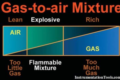
- Lower Explosive Limit (LEL)