Inst ToolsInst ToolsInst Tools
  • Courses
  • Automation
    • PLC
    • Control System
    • Safety System
    • Communication
    • Fire & Gas System
  • Instrumentation
    • Design
    • Pressure
    • Temperature
    • Flow
    • Level
    • Vibration
    • Analyzer
    • Control Valve
    • Switch
    • Calibration
    • Erection & Commissioning
  • Interview
    • Instrumentation
    • Electrical
    • Electronics
    • Practical
  • Q&A
    • Instrumentation
    • Control System
    • Electrical
    • Electronics
    • Analog Electronics
    • Digital Electronics
    • Power Electronics
    • Microprocessor
  • Request
Search
  • Books
  • Software
  • Projects
  • Process
  • Tools
  • Basics
  • Formula
  • Power Plant
  • Root Cause Analysis
  • Electrical Basics
  • Animation
  • Standards
  • 4-20 mA Course
  • Siemens PLC Course
Reading: Move Instruction in Tia Portal
Share
Font ResizerAa
Inst ToolsInst Tools
Font ResizerAa
  • Courses
  • Design
  • PLC
  • Interview
  • Control System
Search
  • Courses
  • Automation
    • PLC
    • Control System
    • Safety System
    • Communication
    • Fire & Gas System
  • Instrumentation
    • Design
    • Pressure
    • Temperature
    • Flow
    • Level
    • Vibration
    • Analyzer
    • Control Valve
    • Switch
    • Calibration
    • Erection & Commissioning
  • Interview
    • Instrumentation
    • Electrical
    • Electronics
    • Practical
  • Q&A
    • Instrumentation
    • Control System
    • Electrical
    • Electronics
    • Analog Electronics
    • Digital Electronics
    • Power Electronics
    • Microprocessor
  • Request
Follow US
All rights reserved. Reproduction in whole or in part without written permission is prohibited.
Inst Tools > Blog > PLC Tutorials > Move Instruction in Tia Portal

Move Instruction in Tia Portal

Last updated: March 4, 2021 11:31 am
Editorial Staff
PLC Tutorials
No Comments
Share
4 Min Read
SHARE

This article is about the use of move instruction with the help of TIA PORTAL.

MOVE instruction plays a huge role in analog programming from changing the speed of the motor to changing temperature intervals, etc.

Move Instruction

Move Instruction in Siemens

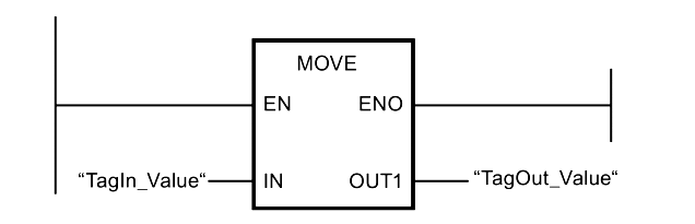
The “Move value” instruction to transfer the content of the operand at input IN to the operand at output OUT1. So the instruction copies the content of operand “TagIn_Value” to operand “TagOut_Value”.

The parameters on the input and output must be of the same data type. The parameters can also be structured tags (PLC data types). It Copies complete arrays and structures.

Do follow the below steps to learn how to work with the MOVE instruction.

Step 1:

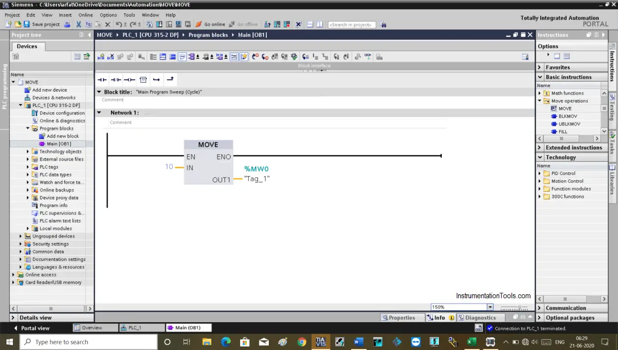
Open TIA PORTAL. Enter in the programming environment. On the left-hand side from the basic instructions menu, you can find a MOVE instruction.

I have added a MOVE instruction as you can see in the below window.

On the Input side, I can use a number, or I can use a variable (like MW, MD) which we want to move to the destination.

So, the input value will go to “OUT1” where you have to define a data type like word, double word, or real.

Here, I have used the word data type.

Say we have a value of “10” at the input side, a value of “10” then moves to the destination address at “OUT1”.

Siemens Move Instruction

Step 2:

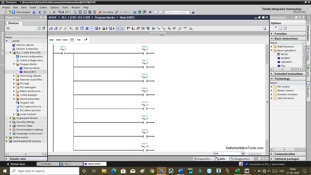
Let’s consider an example where I have to turn ON 8 valves by pressing the start button. In actual programming, this only happens based on conditions like pushing a button.

At first, you may think the logic as shown in the below window. Here, when you press the START switch then all 8 outputs are going to energize.

As a PLC programmer what you need is to make the logic simple, not lengthy, and complicated.
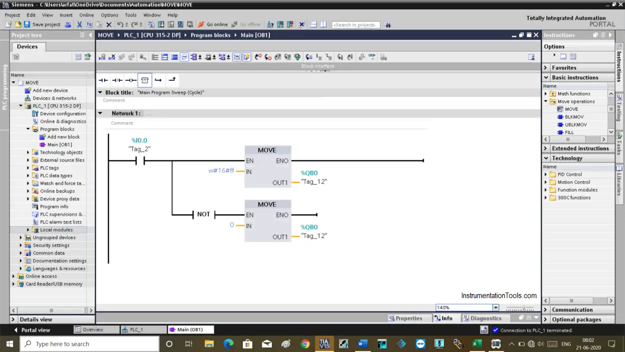
Example of Move Ladder Logic

Step 3:

As you can see in the below window that I have added move instruction to perform the same task as above.

In the network, you can see that I have used w#16#ff.

w#16 is a format you have to add to work with MOVE instruction. The “ff is a hexadecimal number, which represents eight 1’s (11111111) in binary.

When I energize the input, “ff” moved to QBO which holds eight outputs (1 byte = 8 bit). So, all 8 outputs will be turned ON as we sent logic “1” to all.

To reset all the outputs, in the second-line of logic, I have added NOT instruction to inverse the logic.

When NOT is active it will move zero to QBO, which then turns OFF all the outputs.
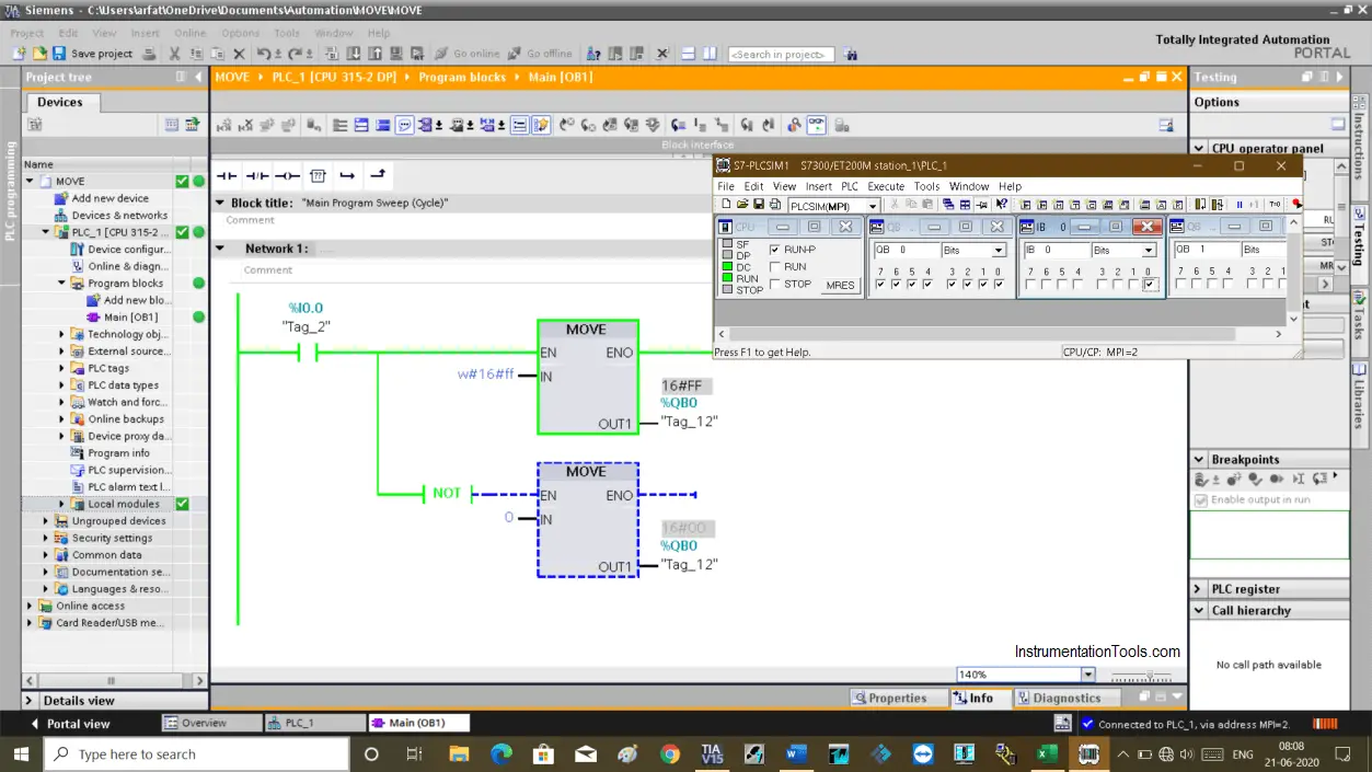
MOVE instructions

Step 4:

Here, you can see the result in the simulator.

when I0.0 is active, then MOVE instruction will move data from “IN” to “OUT1” which in result turning ON all the outputs at the same time.
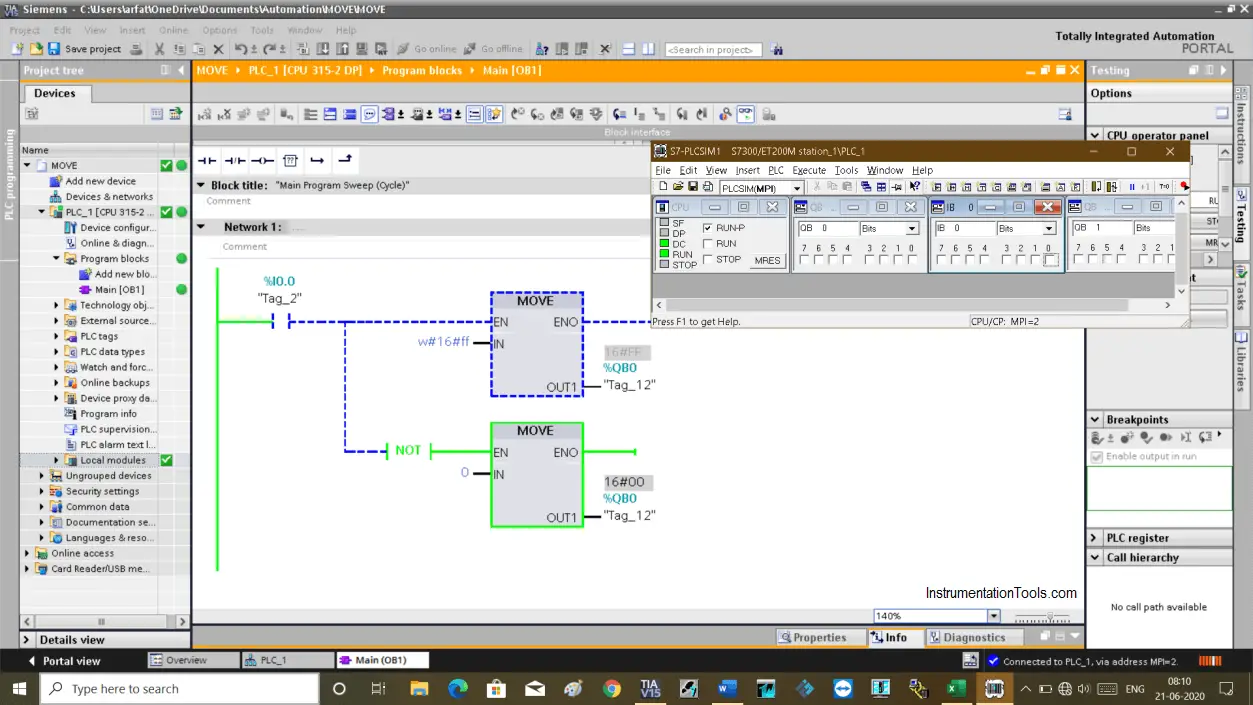
Step 7 basic MOVE instruction

Step 5:

When I0.0 is false, It will move a value of zero from IN to destination location “OUT1” which result in turning OFF all the outputs. (second move instruction block)

Move function block

Author: Suhel Patel

If you liked this article, then please subscribe to our YouTube Channel for PLC and SCADA video tutorials.

You can also follow us on Facebook and Twitter to receive daily updates.

Read Next:

  • One-Shot Rising PLC Logic
  • Digital Logic Functions
  • ON Delay PLC Timer
  • PLC Sequencer Instruction
  • PID in Siemens TIA Portal
Don't Miss Our Updates
Be the first to get exclusive content straight to your email.
We promise not to spam you. You can unsubscribe at any time.
Invalid email address
You've successfully subscribed !

Continue Reading

1 to 8 Demultiplexer PLC ladder diagram
Steps to Configure TCP/IP Communication in Siemens S7-1200 PLC
PLC Commissioning and Testing Procedure (Programmable Logic Controller)
How to use PLC with SQL Database? – Basics & Tutorials
PLC Program to Simulate Gate Array Logic
Electrical and Instrumentation – Automation Pre-engineering Documents
Share This Article
Facebook Whatsapp Whatsapp LinkedIn Copy Link
Share
Leave a Comment

Leave a Reply Cancel reply

Your email address will not be published. Required fields are marked *

Stay Connected

128.3kFollowersLike
69.1kFollowersFollow
210kSubscribersSubscribe
38kFollowersFollow

Categories

Explore More

Siemens LOGO PLC Complete Programming Course
Types of Allen Bradley PLC
Comparing ICS and IT Systems Security
PLC System Site Acceptance Test (SAT)
Programmable Logic Controller Questions and Answers
How to Connect a Solenoid Valve with PLC?
PLC Data Comparison Instructions
PLC Program for Fish Feeding System

Keep Learning

PLC Program to Control Gas Pressure using Closed-Loop

PLC Program to Control Gas Pressure using Closed-Loop

Free Omron PLC Programming Course in HINDI

Free Omron PLC Programming Course in HINDI

PLC Program for Controlling Conveyors ON Sequence and OFF Sequence

PLC Program – Controls Conveyors ON and OFF Sequence

100 PLC Quiz Questions

100 PLC Quiz Questions : True or False

PLC program for Sorting System by Size Example

PLC Based Product Sorting Machine System – Lift Control

Traces in TIA Portal

What is Trace Function in Tia Portal?

PLC Instruction List Code

PLC Instruction List Program for Basic Instructions

OB and FB Blocks in Siemens PLC

Procedure for Siemens S7-300 Download from PC to PLC

Learn More

Digital Electronics Multiple Choice Questions

Fast Adder & Serial Adder Objective Questions – Part 1

PTC NTC Thermistors Comparation

Thermistor Working Principle

Electrical Machines Objective Questions

Electrical Machines Objective Questions

Ideal Diode Characteristics Curve

Difference between ideal diode & conventional diode

Basic components of power electronics

What is Power Electronics? Evolution, Block Diagram, Advantages

Electrical Power Distribution

Electrical Power Distribution

PLC Motor Logic

Interconnection between PLC, MCC, LCP & Pumps – Video

Probe Type Radar Level Transmitter

Contact Type Guided Wave Radar Level Transmitter Working Principle

Menu

  • About
  • Privacy Policy
  • Copyright

Quick Links

  • Learn PLC
  • Helping Hand
  • Part Time Job

YouTube Subscribe

Follow US
All rights reserved. Reproduction in whole or in part without written permission is prohibited.
Welcome Back!

Sign in to your account

Username or Email Address
Password

Lost your password?