Inst ToolsInst ToolsInst Tools
  • Courses
  • Automation
    • PLC
    • Control System
    • Safety System
    • Communication
    • Fire & Gas System
  • Instrumentation
    • Design
    • Pressure
    • Temperature
    • Flow
    • Level
    • Vibration
    • Analyzer
    • Control Valve
    • Switch
    • Calibration
    • Erection & Commissioning
  • Interview
    • Instrumentation
    • Electrical
    • Electronics
    • Practical
  • Q&A
    • Instrumentation
    • Control System
    • Electrical
    • Electronics
    • Analog Electronics
    • Digital Electronics
    • Power Electronics
    • Microprocessor
  • Request
Search
  • Books
  • Software
  • Projects
  • Process
  • Tools
  • Basics
  • Formula
  • Power Plant
  • Root Cause Analysis
  • Electrical Basics
  • Animation
  • Standards
  • 4-20 mA Course
  • Siemens PLC Course
Reading: Why Negative Readings in Gas Detectors ?
Share
Font ResizerAa
Inst ToolsInst Tools
Font ResizerAa
  • Courses
  • Design
  • PLC
  • Interview
  • Control System
Search
  • Courses
  • Automation
    • PLC
    • Control System
    • Safety System
    • Communication
    • Fire & Gas System
  • Instrumentation
    • Design
    • Pressure
    • Temperature
    • Flow
    • Level
    • Vibration
    • Analyzer
    • Control Valve
    • Switch
    • Calibration
    • Erection & Commissioning
  • Interview
    • Instrumentation
    • Electrical
    • Electronics
    • Practical
  • Q&A
    • Instrumentation
    • Control System
    • Electrical
    • Electronics
    • Analog Electronics
    • Digital Electronics
    • Power Electronics
    • Microprocessor
  • Request
Follow US
All rights reserved. Reproduction in whole or in part without written permission is prohibited.
Inst Tools > Blog > Fire & Gas System > Why Negative Readings in Gas Detectors ?

Why Negative Readings in Gas Detectors ?

Last updated: August 21, 2019 5:00 pm
Editorial Staff
Fire & Gas System
No Comments
Share
4 Min Read
SHARE

Why Negative Readings in Gas Detectors ?

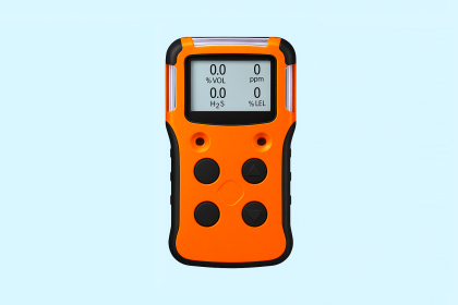
This is a common question that is frequently asked.  As recently as today in fact. So, why do you sometimes see negative readings on your gas detectors/monitor?

All electrochemical or catalytic gas sensors can be prone to both positive and negative drift due to environmental factors such as changes in temperature and humidity.   However these are not the most common causes of negative sensor readings.

Negative sensor readings more commonly occur when your instrument has been “zeroed” in a contaminated atmosphere, where small levels of the sensors’ target gasses are present.   When the instrument is later in a clean-air environment, the sensors will show a negative reading that corresponds to the concentration on the contaminant that was present during the zeroing operation.  For example, if there is 5 PPM carbon monoxide present when the sensor is zeroed, the reading will be -5 PPM when the sensor is returned to clean air.

Negative readings may also occur when the sensor is exposed to a gas that produces a negative cross interference. If a sulfur dioxide sensor, which typically has a -100% cross interference to nitrogen dioxide is exposed to 2 PPM NO2, the resultant sulfur dioxide reading on your instrument will be -2 PPM.

So, does this mean that you should avoid using sensors that have negative cross interferences to each other in the same instrument?  Absolutely not!  If you have NO2 and SO2 present in the same atmosphere, the only way that you can understand the true concentration of each gas is by having both sensors. In the example that we used above, if your atmosphere contained 2 PPM SO2 along with the 2 PPM NO2, the resultant SO2 reading due to the negative cross interference would be zero. The only way that you could know that you have 2 PPM SO2 present is by recognizing the presence of the NO2 gas and understanding its effect on the SO2 sensor. Eliminating one of the sensors from the instrument does not eliminate the hazard that it, and you, are being exposed to!

We will sometimes say that they have never seen a negative reading on an instrument before but they have recently changed monitors and now seem to see them all the time. This is because some manufacturers believe that negative readings only confuse users and mask them from their instruments. All negative readings are displayed as zero. This is a practice that can in fact serve to mask you from seeing and recognizing the hazards that exist. If an H2S sensor has an offset of -10 PPM due to drift or a false zero operation that has been masked by the manufacturer, exposure in a true concentration of +10 PPM will still produce a zero reading and a concentration of +20 PPM would only be displayed as 10. This situation would be easier to recognize if the negative reading was normally displayed in the first place.

So, while negative readings are puzzling and uncomfortable to most gas monitor users, they are not always a bad thing. If you understand the circumstances that cause the negative readings, you will get more information from your instrument and have a better understanding of the environment you are working in.

Author  : Dave

Source : indsci
Don't Miss Our Updates
Be the first to get exclusive content straight to your email.
We promise not to spam you. You can unsubscribe at any time.
Invalid email address
You've successfully subscribed !

Continue Reading

Gas Detectors Working Principle
What are Linear Heat Detectors?
Smoke Detector Testing Procedure
Catalytic Type Gas Sensor Principle
Fire and Gas System Loop Checks Procedure
Rate of Rise Thermal Detectors Working Principle
Share This Article
Facebook Whatsapp Whatsapp LinkedIn Copy Link
Share
Leave a Comment

Leave a Reply Cancel reply

Your email address will not be published. Required fields are marked *

Stay Connected

128.3kFollowersLike
69.1kFollowersFollow
210kSubscribersSubscribe
38kFollowersFollow

Categories

Explore More

Chlorine Gas Hazards
What is Photoionization Detector (PID)?
Manual Call Point Testing Procedure
Basics of Fire Fighting Hydrant Systems
MOS Type Gas Sensor Principle
Industrial Flame Detectors
What is Gas Suppression Systems ?
Fixed Temperature Heat Detector Working Principle

Keep Learning

Fire Alarm System Questions

Interview Questions on Fire Alarm System

Beam-Detectors-Working-Principle-2

Beam Detectors Working Principle Animation

Transformer Protection using fire water spray system

Fire Water Spray Systems Principle

Which Gases Can a Multi-Gas Detector Detect

Which Gases Can a Multi-Gas Detector Detect?

Gas Detectors Practical Problems and Troubleshooting

Gas Detectors Practical Problems and Troubleshooting

Flame Detector Testing Procedure

Flame Detector Testing Procedure

Addressable Fire Alarm System

Which One is Best – Conventional or Addressable Fire Alarm System?

Fire and Gas System Interview Questions & Answers

Fire and Gas System Interview Questions & Answers

Learn More

ISA symbols for Process Instrumentation

ISA Codes & Symbols for Process Instrumentation

Transformer voltage and turns ratio

Transformer Voltage Ratio

Rotary Stem Valves

Rotary Stem Valves

Stepper Motor Construction

Stepper Motor Basics, Types, Modes, Wiring, Questions

Omron PLC for Product Painting with Integrated Weighing System

Omron PLC for Product Painting with Integrated Weighing System

Troubleshooting Fluid Systems Pressure Changes

Troubleshooting Fluid Systems Pressure Changes

Overview of Resistor

The Information About Resistor Color Code You Should Know

Argonite Fire Suppression System Animation

Argonite Fire Suppression System Working Principle

Menu

  • About
  • Privacy Policy
  • Copyright

Quick Links

  • Learn PLC
  • Helping Hand
  • Part Time Job

YouTube Subscribe

Follow US
All rights reserved. Reproduction in whole or in part without written permission is prohibited.
Welcome Back!

Sign in to your account

Username or Email Address
Password

Lost your password?