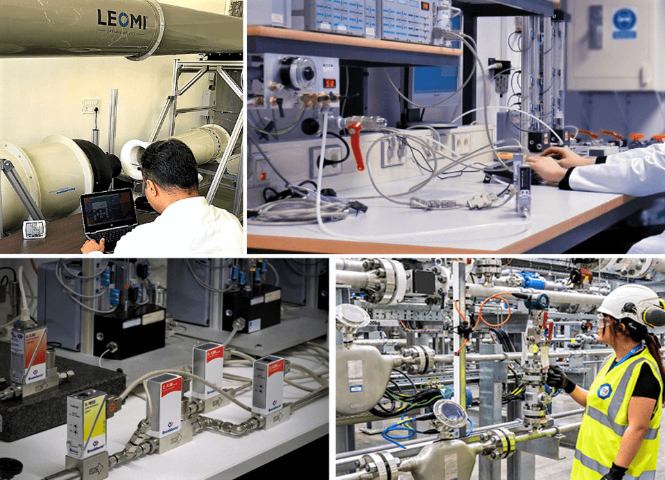
A gas flow meter is used to measure the volumetric or mass flow rate of various process gases in industrial plants and machinery. The flow rate refers to the speed at which fluid is moving through closed pipes or ducts at a given time.
Modern instrumentation & control engineering design needs monitoring of fluid flow rates to optimize the use of gases and improve the efficiency of processes and equipment. Therefore, a gas flow meter device must be calibrated against a reference or a master calibration system.
Due to process & environmental conditions, flowmeters may have some drift in flowrate readings which needs recalibration periodically for the flow range it is designed for, to achieve the desired accuracy for smooth process operation.
Some organizations have an ISO audit system in place which needs recalibration at a specific time frame.
Types of Gas Flow Meters Available in the Market
Various flowmeter technologies are available currently in the market which need to be calibrated and there are different methods for calibration based on product design.
- Turbine flowmeter
- Vortex flowmeter
- Coriolis flowmeter
- Thermal Mass flowmeter
- Ultrasonic flowmeter
and there are different methods for calibration based on product design.
Types of Calibration Procedures
Gas flowmeter calibration systems mainly depend on product technology to be calibrated.
Some widely used calibration procedures are as below
- Reference Master Meter calibration
- Primary Air by Bell / Piston prover calibration
- Critical Flow Venturi (Sonic nozzle) calibration
- Wind Tunnel Air Velocity calibration
- Onsite validation by calibrated reference gas flowmeter
Gas flow meter calibration is done as per above various calibration systems which involve comparison and adjustment of the flowmeter under test confirming to National & International standards mainly following ISO 17025 standards for calibration methods.

Reference Master Meter Calibration Procedure
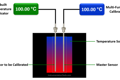
Reference Master meter calibration compares with duly calibrated master gas flowmeter traceable to national accredited calibration laboratories with a gas flowmeter under test at desired flow ranges and adjusts its calibration as per desired accuracy tolerances.
Reference Master meter calibration steps
- Place the reference master meter in series with the flow meter under test.
- Compare the readings of the master flow meter and flow meter using air or standard gas flow rate with a close loop calibrated volumetric tank storage system.
- Calibrate the flowmeter under test to conform with the master flow meter calibration.
Piston / Bell Prover Gravimetric Calibration Procedure
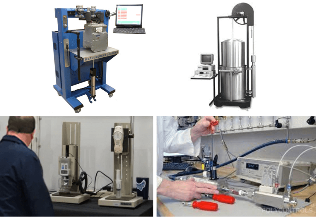
Gravimetric calibration is one of the most accurate and cost-effective volumetric and gas mass flow meter calibration procedures at low pressure.
Piston prover-based gravimetric method is ideal for gases for low flow rates whereas Bell Prover calibration is mainly used for a high flow rate of air calibration.
The calibration flow laboratory is always maintained at controlled ambient conditions such as temperature, humidity for master flow meters’ best performance.
In the piston or bell prover flow meter calibration procedure, a known volume of fluid is forced through a flow meter under test. The piston/bell prover is a cylindrical device with a known internal diameter.
The piston/bell prover contains a piston/ bell which produces volumetric flow by positive displacement.
The piston prover method is ideal for Low flow rate gas or liquid thermal mass flow controller, ultrasonic flow meter & turbine flow meter calibration to a high degree of accuracy.
Piston / Bell prover Gravimetric calibration steps
- Fix the flowmeter in a series of piston / bell prover systems for calibration.
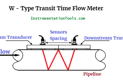
- Desired gas flow via test flowmeter enters in the piston / bell prover which will move piston / bell upwards with detecting distance between sensors for known volume between is measured.
- Measuring travel time, pressure, temperature and flow rate at reference conditions is calculated via software systems.
- Compare the calculated flow rate with the flowmeter under test and adjust it to the measured flow rate.
*Typical
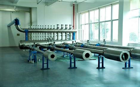
Critical Flow Venturi (Sonic Nozzle) Calibration Procedure
Critical Flow Venturi Nozzle (Sonic Nozzles) is used for different flow rate capacities designed as per ISO 9300:2015 as a reference standard.
Sonic nozzles are considered the best reference standard for calibration of precision flow meters used for custody transfer.
Gas flow accelerates to the critical velocity at the throat (known as sonic velocity) where it will reach a steady flow state of single-phase gases.
This sonic velocity is a specific point velocity at a certain pressure which is accurate as a reference velocity for calibrating a flowmeter under test. It is used for almost all fixed type flowmeters mainly vortex flowmeter, turbine flowmeter, thermal mass flowmeter, Coriolis flowmeter, etc.
Sonic nozzle calibration steps
- Fix the flowmeter in series of the pipeline where calibrated sonic nozzle
- Start air compressor in the testing system
- When sonic velocity reaches the measuring section, the flowmeter under calibration needs to adjust its reading & set it. Repeat the same steps for different sonic velocity points for specific flow rate.
- Comparing flow rate from sonic nozzle with flow meter under calibration.
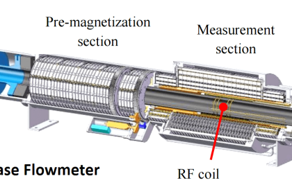
Wind Tunnel Calibration Procedure
The wind tunnel is designed for characterization of air velocity, air turbulence for various different turbomachinery, and instruments calibration and simulation.
There are different proprietary & standard designs of wind tunnels installed. It has an open test chamber for calibration or test of the device under test.
It is widely used for various types of flow sensor calibration such as hot-wire/vane anemometer, insertion thermal mass flowmeter, pitot tube, measuring probes, etc.
Wind tunnel calibration steps
- Install a flow sensor probe in the test chamber with desired insertion depth and correct orientation.
- Step by step increasing reference velocity and measure & record flow sensor under test.
- Based on reference velocity, plot a curve and suitable interpolation & extrapolation flow calculations upload curve into device under test.
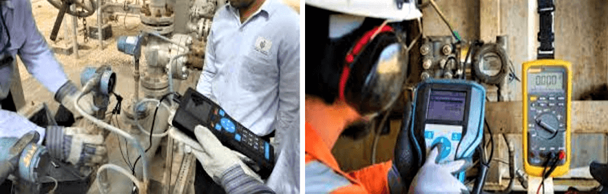
Onsite Validation & Calibration Procedure
Onsite validation and calibration of gas flow meters are also possible in some industrial applications. This method is not accurate as of the above methods but can validate gas flowmeters in use having high errors or non-repeatability.
Mainly two ways are possible for onsite validation
- Pump-up test with pressure vessel
- With calibrated reference gas flowmeter to be installed in series
Pump-up test steps
- Pressure vessel in series of gas flowmeter
- Start Gas flow and note gas flow meter reading and timer for filling pressure vessel
- Pressure vessel pressure with respect to volume capacity and gas flow meter totaliser to be compared
- Validation is done by comparing both results and errors.
Calibrated reference gas flowmeter
- Install calibrated reference gas flowmeter in series of gas flowmeter under validation
- Compare both flowmeter result and compute error
For any technical queries, we would be pleased to provide you related information. Contact us: Leomi