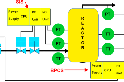
In Safety Instrumented System (SIS) Instrument, installing a Partial stroke testing device (PSD) in the SIS final element viz. in Automated on/off valve helps to improve the Proof test requirements.
The PSD is an intelligent electronic field instrument, configured to initiate, control, and monitor in an automatic way the partial movement of the on/off valve, which moves from the normal operating point towards the safe position. The valve travels partially in a safe manner not to disrupt the running system.
Stores the gathered data and communicates in a digital way with remote data management systems.
Benefits of Partial Stroke Testing
- The Diagnostic Coverage (DC factor) on a valve increase, that helps in :
- Increase of proof test frequency.
- The probability of Failure on Demand (PFD) of the valve assembly gets reduced.
- With calculation, a single valve with Partial Stroking Device support is sufficient instead of dual valves.
- 1oo2 solutions possible instead of further higher configurations.
- It helps to maintain the normal run periods between two planned stops.
- Have a higher overall safety because of better Safe Failure Fraction (SFF).
- Lowers the maintenance cost and minimizes human errors.
Partial Stroke Testing Device (PSD)
Design considerations to be taken into account with Partial Stroke Testing Device (PSD).
Below are a few essential points to be considered while designing a valve with a Partial Stroke testing device.
- Valve technology and desired valve configuration.
- Valve assembly failure rates (valve technology and application related).
- Diagnostic coverage and SFF with and without the use of PSD
- Safety Integrity Level gap to be closed by final element
- The desired target for proof test interval:
- Proposed test interval if PSD would be used.
- Valve seat leakage (tightness) class.
- Ascertain whether the application can allow partial stroke testing of the valve while in service.
- Valve Failure scenario items, distribution, and nature of failures.
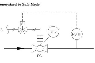
- Valves that stay in the same position for more than 6 months need to be designed according to Long Stand Still requirements, a partial stroke test device may be included.
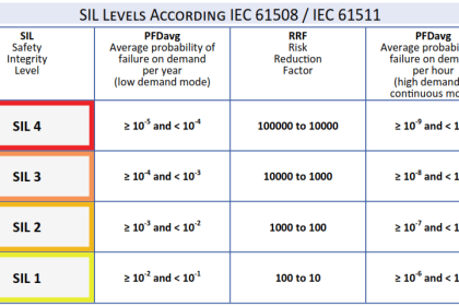
Impact of Probability of Failure on Demand (PFD)
- By including partial stroke devices to detect potential failures before they become dangerous.
- PFD(1oo1) = DC.λd .(MTTR + TIa/2) + (1-DC).λd.(TIm/2)
Where,
λd = dangerous failure rate
TIa = Partial stroke test interval
TIm = Test interval manual testing
DC = Diagnostic Coverage Factor
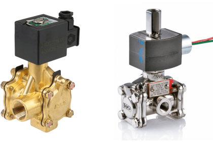
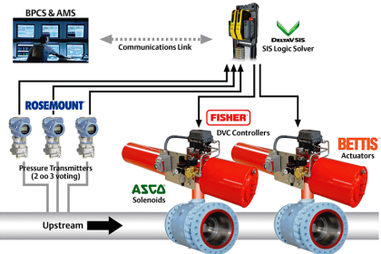
Typical Installation
Below is narrated an example by a specific manufacturer for understanding the partial stroke testing device PSD installation concepts, it may vary with different manufacturers.
Metso Neles Valveguard (Partial Stroke Testing Device)
Wiring and installation scheme for installation of Partial stroking device is typical with many installations as detailed below.
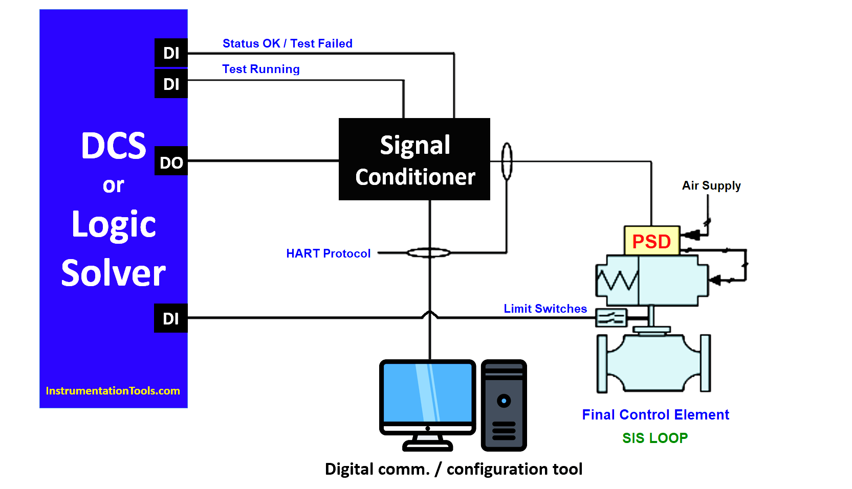
- 2 wire loop from SIS to PSD. PSD loop powered.
- Solenoid function included in PSD.
- Device type A according to IEC 61508 (total device).
- PSD shall be certified for use up to SIL3
- PSD DI feedback signals are: – Test start warning.
- Indication of PSD status/valve assembly.
- Partial stroke testing can be initiated in 3 ways: Using local display, PSD, Thru HART communicator & Automatic configuration from the controller.
- PSD installed such that it is close coupled to actuator + external valve end position switches.
Conclusion
Thus installing a Partial stroke testing device (PSD) in the SIS final element, helps to improve the Proof test requirements. It is recommended to go for PSD wherever the SIS valves can’t be tested under scheduled proof test intervals by taking careful consideration of the process needs.
If you liked this article, then please subscribe to our YouTube Channel for Electrical, Electronics, Instrumentation, PLC, and SCADA video tutorials.
You can also follow us on Facebook and Twitter to receive daily updates.
Read Next:
- BPCS Control System
- SIS Instrument Sharing
- Automated Block Valves
- SIS Application Program
- Safety System Maintenance