Inst ToolsInst ToolsInst Tools
  • Courses
  • Automation
    • PLC
    • Control System
    • Safety System
    • Communication
    • Fire & Gas System
  • Instrumentation
    • Design
    • Pressure
    • Temperature
    • Flow
    • Level
    • Vibration
    • Analyzer
    • Control Valve
    • Switch
    • Calibration
    • Erection & Commissioning
  • Interview
    • Instrumentation
    • Electrical
    • Electronics
    • Practical
  • Q&A
    • Instrumentation
    • Control System
    • Electrical
    • Electronics
    • Analog Electronics
    • Digital Electronics
    • Power Electronics
    • Microprocessor
  • Request
Search
  • Books
  • Software
  • Projects
  • Process
  • Tools
  • Basics
  • Formula
  • Power Plant
  • Root Cause Analysis
  • Electrical Basics
  • Animation
  • Standards
  • 4-20 mA Course
  • Siemens PLC Course
Reading: Transmitter Proof Testing
Share
Notification Show More
Font ResizerAa
Inst ToolsInst Tools
Font ResizerAa
  • Courses
  • Design
  • PLC
  • Interview
  • Control System
Search
  • Courses
  • Automation
    • PLC
    • Control System
    • Safety System
    • Communication
    • Fire & Gas System
  • Instrumentation
    • Design
    • Pressure
    • Temperature
    • Flow
    • Level
    • Vibration
    • Analyzer
    • Control Valve
    • Switch
    • Calibration
    • Erection & Commissioning
  • Interview
    • Instrumentation
    • Electrical
    • Electronics
    • Practical
  • Q&A
    • Instrumentation
    • Control System
    • Electrical
    • Electronics
    • Analog Electronics
    • Digital Electronics
    • Power Electronics
    • Microprocessor
  • Request
Follow US
All rights reserved. Reproduction in whole or in part without written permission is prohibited.
Inst Tools > Blog > Safety Instrumented System (SIS) > Transmitter Proof Testing

Transmitter Proof Testing

The purpose of proof testing is to detect the failures within the transmitter that are not detected by the regular diagnostics.

Last updated: November 12, 2020 7:26 pm
Editorial Staff
Safety Instrumented System (SIS)
No Comments
Share
3 Min Read
SHARE

The purpose of proof testing is to detect the failures within the transmitter that are not detected by the regular diagnostics of the transmitter. Of main concern are undetected failures that prevent the safety instrumented function from performing its intended function.

Contents
Proof Testing MethodAnalog Output Loop Test

Proof Testing Method

Transmitter Proof Testing

The frequency of the proof tests (or the proof test interval) is to be determined in the reliability calculations for the safety instrumented functions for which the transmitter is applied. The actual proof tests must be performed more frequently or as frequently as specified in the calculation in order to maintain the required safety integrity of the safety instrumented function.

The following tests need to be specifically executed when a proof test is performed. The results of the proof test need to be documented and this documentation should be part of a plant safety management system. Failures that are detected should be reported to the manufacturer.

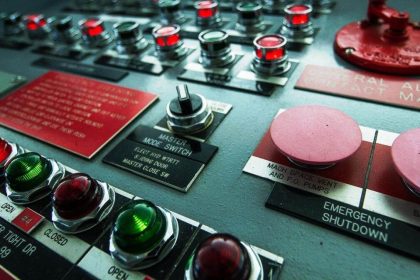
The personnel performing the proof test of the transmitter should be trained in SIS operations including bypass procedures, transmitter maintenance, and company management of change procedures.

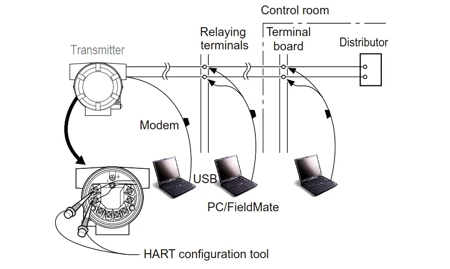
Tools required: Handheld terminal (HART)

Analog Output Loop Test

1. Bypass the safety PLC or take other appropriate action to avoid a false trip.

2. Send a HART command to the transmitter to go to the high alarm current output and verify that the analog current reaches that value.

3. Send a HART command to the transmitter to go to the low alarm current output and verify that the analog current reaches that value.

4. Use the HART communicator to view detailed device status to ensure no alarms or warnings are present in the transmitter.

5. Perform reasonability check on the sensor value(s) versus an independent estimate (i.e. from direct monitoring of BPCS value) to show current reading is good.

6. Restore the loop to full operation.

7. Remove the bypass from the safety PLC or otherwise restore normal operation.

Remarks The output needs to be monitored to assure that the transmitter communicates the correct signal.

Source: Yokogawa

Don't Miss Our Updates
Be the first to get exclusive content straight to your email.
We promise not to spam you. You can unsubscribe at any time.
Invalid email address
You've successfully subscribed !

Continue Reading

Difference between Availability, Reliability & SIL
Understanding Safety Integrity Level IEC 61511
What is Emergency Shutdown System (ESD) ?
SIS Sensors
S84 / IEC 61511 Standard for Safety Instrumented Systems
Safety Instrumented Burner Management System
Share This Article
Facebook Whatsapp Whatsapp LinkedIn Copy Link
Share
Leave a Comment

Leave a Reply Cancel reply

Your email address will not be published. Required fields are marked *

Stay Connected

128.3kFollowersLike
69.1kFollowersFollow
210kSubscribersSubscribe
38kFollowersFollow

Categories

Explore More

SIS Bypass and Impairment – Safety Instrumented System
Why choose Intrinsic Safety ?
Difference between SIS, PLC and BPCS Systems
Process Safety and Instrumentation
What is Shutdown Valve?
Probability of Failure on Demand (PFD)
Concept of Redundancy in Control Systems
De-energize to Safe Loop philosophy

Keep Learning

PRV

Direct-actuated Safety and Relief Valves

Failure Demand in Safety Control Circuit

Safety Instrumented System Module Failure

Logic Solver in Safety PLC

What is a Logic Solver? – Safety PLC

SIS Testing and Repair Deferral

SIS Testing and Repair Deferral

Emergency ShutDown Valve Working Principle

ESDV : How it Works ?

Smart Valve Monitoring

SIS Instruments and Valves Inline Testing – Safety Instrumented System

Partial Stroke Testing Device (PSD) in SIS Final Control Element

Partial Stroke Testing Device (PSD) in SIS Final Control Element

Safety Control System

What is Safety Control System ?

Learn More

PLC Engineers Interview Questions

PLC SCADA Engineers Interview Questions and Answers

Differential Pressure Switch Calibration Procedure - Copy

Differential Pressure Switch Calibration Procedure

Code Block Comparison

Compare Online and Offline PLC Programs

DCS Vs PLC

DCS versus PLC Architecture

Relay-Operation

Relay Working Animation

Control valve positioner calculation

Calculate Control Valve Stem Position

Gases LEL and UEL

What is Lower Explosive Limit & Upper Explosive Limit ?

PLC Program to Count and Pack Parts from conveyor

Count and Pack Objects from Conveyor using PLC Ladder Logic

Menu

  • About
  • Privacy Policy
  • Copyright

Quick Links

  • Learn PLC
  • Helping Hand
  • Part Time Job

YouTube Subscribe

Follow US
All rights reserved. Reproduction in whole or in part without written permission is prohibited.
Welcome Back!

Sign in to your account

Username or Email Address
Password

Lost your password?