Inst ToolsInst ToolsInst Tools
  • Courses
  • Automation
    • PLC
    • Control System
    • Safety System
    • Communication
    • Fire & Gas System
  • Instrumentation
    • Design
    • Pressure
    • Temperature
    • Flow
    • Level
    • Vibration
    • Analyzer
    • Control Valve
    • Switch
    • Calibration
    • Erection & Commissioning
  • Interview
    • Instrumentation
    • Electrical
    • Electronics
    • Practical
  • Q&A
    • Instrumentation
    • Control System
    • Electrical
    • Electronics
    • Analog Electronics
    • Digital Electronics
    • Power Electronics
    • Microprocessor
  • Request
Search
  • Books
  • Software
  • Projects
  • Process
  • Tools
  • Basics
  • Formula
  • Power Plant
  • Root Cause Analysis
  • Electrical Basics
  • Animation
  • Standards
  • 4-20 mA Course
  • Siemens PLC Course
Reading: DP Level Transmitters Compensation Techniques
Share
Font ResizerAa
Inst ToolsInst Tools
Font ResizerAa
  • Courses
  • Design
  • PLC
  • Interview
  • Control System
Search
  • Courses
  • Automation
    • PLC
    • Control System
    • Safety System
    • Communication
    • Fire & Gas System
  • Instrumentation
    • Design
    • Pressure
    • Temperature
    • Flow
    • Level
    • Vibration
    • Analyzer
    • Control Valve
    • Switch
    • Calibration
    • Erection & Commissioning
  • Interview
    • Instrumentation
    • Electrical
    • Electronics
    • Practical
  • Q&A
    • Instrumentation
    • Control System
    • Electrical
    • Electronics
    • Analog Electronics
    • Digital Electronics
    • Power Electronics
    • Microprocessor
  • Request
Follow US
All rights reserved. Reproduction in whole or in part without written permission is prohibited.
Inst Tools > Blog > Level Measurement > DP Level Transmitters Compensation Techniques

DP Level Transmitters Compensation Techniques

Last updated: December 8, 2016 10:40 am
Editorial Staff
Level Measurement
3 Comments
Share
4 Min Read
SHARE

It would be idealistic to say that the DP Level Transmitters can always be located at the exact the bottom of the vessel where we are measuring fluid level in. Hence, the measuring system has to consider the hydrostatic pressure of the fluid in the sensing lines themselves. This leads to two compensations required.

Zero Suppression

In some cases, it is not possible to mount the level transmitter right at the base level of the tank. Say for maintenance purposes, the level transmitter has to be mounted X meters below the base of an open tank as shown in below figure.

Level Transmitter with Zero Suppression

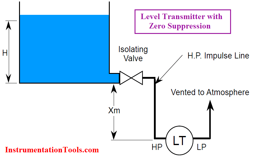
The liquid in the tank exerts a varying pressure that is proportional to its level H on the high-pressure side of the transmitter. The liquid in the high pressure impulse line also exerts a pressure on the high-pressure side. However, this pressure is a constant (P = S – X) and is present at all times. When the liquid level is at H meters, pressure on the high-pressure side of the transmitter will be:

Phigh = S⋅H + S⋅ X + Patm

Plow = Patm

ΔP = Phigh – Plow = S⋅H + S⋅ X

That is, the pressure on the high-pressure side is always higher than the actual pressure exerted by the liquid column in the tank (by a value of S⋅ X). This constant pressure would cause an output signal that is higher than 4 mA when the tank is empty and above 20 mA when it is full. The transmitter has to be negatively biased by a value of -S⋅ X so that the output of the transmitter is proportional to the tank level (S⋅H) only. This procedure is called Zero Suppression and it can be done during calibration of the transmitter.

Zero Elevation

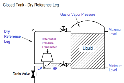
When a wet leg installation is used (see below Figure), the low-pressure side of the level transmitter will always experience a higher pressure than the high-pressure side. This is due to the fact that the height of the wet leg (X) is always equal to or greater than the maximum height of the liquid column (H) inside the tank.

Level Transmitter with Zero Elevation

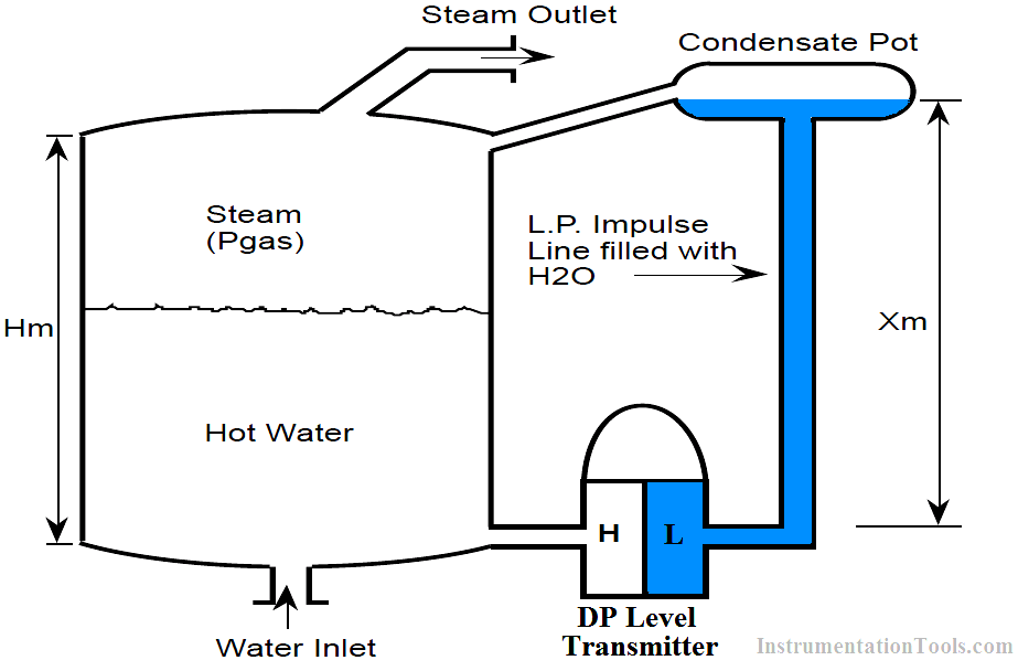
When the liquid level is at H meters, we have:

Phigh = Pgas + S⋅H

Plow = Pgas + S⋅ X

ΔP = Phigh – Plow = S⋅H – S⋅ X = – S (X – H)

The differential pressure ΔP sensed by the transmitter is always a negative number (i.e., low pressure side is at a higher pressure than high pressure side). ΔP increases from P = -S⋅ X to P = -S (X-H) as the tank level rises from 0% to 100%.

If the transmitter were not calibrated for this constant negative error (-S⋅ X), the transmitter output would read low at all times.

To properly calibrate the transmitter, a positive bias (+S⋅ X) is needed to elevate the transmitter output.

This positive biasing technique is called zero elevation.

Don't Miss Our Updates
Be the first to get exclusive content straight to your email.
We promise not to spam you. You can unsubscribe at any time.
Invalid email address
You've successfully subscribed !

Continue Reading

Wrong Installation of Horn Type Radar Level Transmitter on Sloping Tank
Ultrasonic Level Transmitter Animation
Open and Closed Tank Level Calculations
Cable Float Level Switch Working Principle
Laser Level Measurement Principle
Displacer Level Transmitter Dry Calibration with Weights
Share This Article
Facebook Whatsapp Whatsapp LinkedIn Copy Link
Share
3 Comments
  • prahalanathan.k says:
    December 17, 2016 at 4:27 pm

    hai
    this is very useful for all instrument guys ur way of presentation would be appreciate keep on always
    thanks

    Reply
  • SANDEEP MEHTA says:
    June 23, 2018 at 7:40 pm

    Sir,
    I had referred modules of level transmitter & i can’t understand a particular line that “LP side posses higher pressure higher than HP side”, then how can we say that side as low pressure side.

    Reply
  • SANDEEP MEHTA says:
    June 24, 2018 at 5:19 pm

    Ya well I got it.

    Reply

Leave a Reply Cancel reply

Your email address will not be published. Required fields are marked *

Stay Connected

128.3kFollowersLike
69.1kFollowersFollow
210kSubscribersSubscribe
38kFollowersFollow

Categories

Explore More

Displacer Level Transmitter 5-point Calibration
TDR & FMCW Radar Level Transmitters Principle
Displacer Level Transmitter Working Principle
Level Measurement with Wet leg and Installed Below Tapping Point
Advantages & Disadvantages of Level Measurement Systems
What is the Simple Alternative Vessel Level Indication?
Stilling Wells for Level Measurement
Level Troll working principle

Keep Learning

interface-level-measurement-need

Level Measurement Terminology

Capacitive Level Switch Principle

Capacitive Level Switch Principle

Contact and Non-Contact Level Sensors

Contact and Non-Contact Level Sensors

Micro-impulse Level Transmitter Principle

Micro-impulse Level Transmitter Principle

Ultrasonic Level Transmitters Installation

Ultrasonic Level Transmitter Principle, Limitations, Calibration and configuration

level gauge

Basics of Sight Glass Level Gauge

non-contact and guided-wave radar level transmitters

Radar Level Measurement

Level Calculation with Remote Seals

Level Calculation with Remote Seals

Learn More

Control Valves Multiple Choice Questions

Control Valves Multiple Choice Questions

Magnetic Float Level Switch Working Animation

Sensors and Transducers Objective Questions

Transducers Objective Questions

Electrical Machines Objective Questions

Electrical Machines MCQ Series 23

plc-analog-input-card-conversion-formula

PLC Analog Input Conversion Formula

Electrical Machines Questions and Answers

Synchronous Motor Phasor Diagram Questions

Digital Electronics Objective Questions

Digital Electronics Objective Questions – Set 10

Tie rods double acting cylinder

What is a Pneumatic Cylinder?

Menu

  • About
  • Privacy Policy
  • Copyright

Quick Links

  • Learn PLC
  • Helping Hand
  • Part Time Job

YouTube Subscribe

Follow US
All rights reserved. Reproduction in whole or in part without written permission is prohibited.
Welcome Back!

Sign in to your account

Username or Email Address
Password

Lost your password?