In Safety Instrumented System (SIS), safety requirements follow the specifications prescribed in the below sections.
These requirements shall be sufficient to design the SIS and shall include a description of the intent and approach applied during the development of the SIS safety requirements as applicable.
SIS Safety Requirements
SIS safety requirements follow the general norms prescribed below.
- Safety Requirements Specification – Describes the function of the protective layer & Provides design details.
- Safety Requirements Specifications are taken from – LOPA, Team members involved in safety design
- Safety Requirement Specifications documented in – Safety Requirements Specification detailed documentation, Safety Requirements Specification (SRS) form, LOPA database, or workbooks.
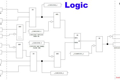
- SIF description of all the necessary LOPA scenarios with required logic to achieve the required functional safety (e.g., a cause and effect diagram, logic narrative)
- Assumed sources of demand and demand rate on each SIF.
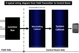
- Process plant input and output devices list related to each SIF which is identified by the plant by means of equipment identification (e.g., field tag list) and all of them marked in P&ID.
- List the requirements to identify and take account of common cause failures,
- Define the safe state of the process for each identified SIF, elaborate on a steady state to be achieved and the specified hazardous event has been avoided or sufficiently mitigated
- Definition of any individually safe process states which, when occurring concurrently, create a separate hazard (e.g., overload of emergency storage, multiple relief to flare system);
- Requirements detailing the proof test intervals
- Requirements relating to proof test implementation
- Response time requirements for each SIF to bring the process to a safe state within the process safety time
- Describe all SIS elements – process measurements, range, accuracy, and their trip set points
- List SIF process output actions and the criteria for successful operation, e.g., Allowable seat leakage rate for final control element on/off valves
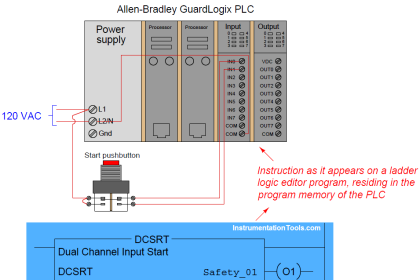
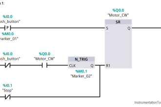
- The functional relationship between process inputs and outputs, including logic, mathematical functions, and any required permissive for each SIF including the time constants, correction factors for input sensors, etc.
- List the requirements for manual shutdown for each SIF
- List all requirements relating to energize or de-energize to trip for each SIF;
- Describe the requirements for resetting each SIF after an emergency shutdown (e.g., requirements for manual, semiautomatic, or automatic final element resets after trips
- Update the maximum allowable spurious trip rate for each SIF
- Narrate all failure modes for each SIF and desired response of the SIS (e.g., alarms, automatic shutdown)
- List the required SIL and mode of operation (demand/continuous) for each SIF
- Explain any specific requirements related to the procedures for starting up and restarting the SIS.
- Description of the modes of operation of the plant and requirements relating to SIF operation within each mode;
- Application program safety requirements as listed in relevant safety documentation.
- Define the requirements for bypasses including written procedures to be applied during the bypassed state that describes how the bypasses will be administratively controlled and then subsequently cleared
- List all interfaces between the SIS and any other system (including the BPCS and operators);
- Specify the requirements of Operator response to alarms.
- Specify any action necessary to achieve or maintain a safe state of the process in the event of a fault(s) being detected in the SIS, taking into account all relevant human factors and the mean repair time which is feasible for the SIS.
- Ensure to take into account travel time, location, spares availability, service personnel availability, and environmental constraints
- Identify all of the dangerous combinations of output states of the SIS that need to be avoided
- Identify all extremes of environmental conditions that are likely to be encountered by the SIS during shipping, storage, installation, and operation. This may require consideration of the following: temperature, humidity, contaminants, etc. Besides electrical grounding, electromagnetic interference/radio frequency interference (EMI/RFI), shock/vibration, electrostatic discharge, electrical area classification, flooding, lightning, and other related factors are to be taken in mind.
- Identify normal and abnormal process operating modes for both the plant as a whole (e.g., plant start-up) and individual plant operating procedures (e.g., equipment maintenance, sensor calibration, or repair). Additional SIFs may be required to support these process operating modes.
- Define the requirements for any SIF necessary to overcome any major accident event, e.g., the time required for a valve to remain operational in the event of a fire.
Conclusion
SIS designers/reviewers to consider the above requirements while designing Safety Instrumented systems and Safety Functions. This helps for robust SIS for the safe operation of plant facilities.
If you liked this article, then please subscribe to our YouTube Channel for Electrical, Electronics, Instrumentation, PLC, and SCADA video tutorials.
You can also follow us on Facebook and Twitter to receive daily updates.
Read Next:
- Audit & Assessment in SIS
- SIS Hardware Fault Tolerance
- ERP in Industrial Automation
- Bypass and Impairment in SIS
- SIS Testing and Repair Deferral
