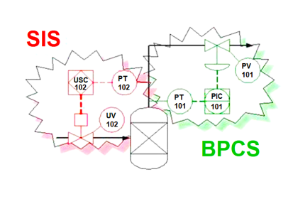
In Safety Instrumented System (SIS), Proof testing is very critical to ensure all SIS Sensors. Logic solver & Final control elements are functioning healthily as designed.
Various International Standards such as IEC, ISA & ANSI govern the requirements of SIS Proof testing.
What is Proof Testing?
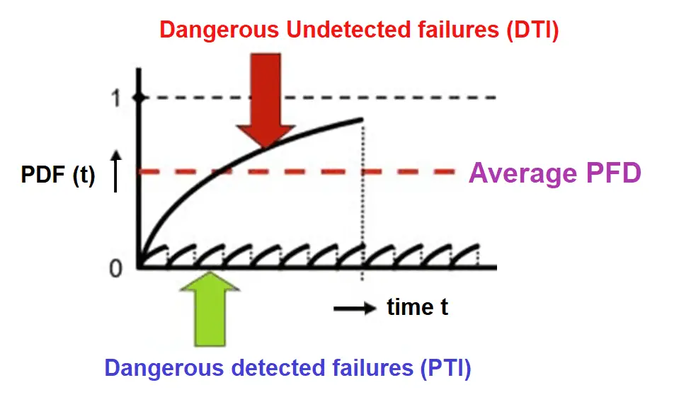
Proof testing is a test performed to reveal undetected faults in a Safety
Instrumented System. So in case of any instrument/system deterioration, the system can be restored to its designed functionality as per IEC-61511 standards.
Why Proof Testing is Important?
Proof testing is crucial for the plant’s safe operation without any potential hazard due to the lack of all SIS instruments’ performance as per the SIS design intent.
Proof testing supports early detection of failure, so that failure can be attended to as quickly as possible and maintain the SIS functionality much more reliable.
In the event of not performing a Proof test on the SIS instruments as per the SIS calculations, it may lead to Dangerous failure which may eventually end up in catastrophic events.
Proof Test Requirements
Below project upgrade/modification activities involving Safety Instrumented system requires to perform proof testing.
- Introducing new process lines involving SIS Instruments
- Changing the SIS configuration
- Adding flush and drain valves where SIS transmitters/Final control elements are in place.
- Adding block and bypass valves with Upstream/Downstream isolations.
During SIS Design proper care to be taken after finalizing the SIS configuration based on the PHA/LOPA outcome which may end up in
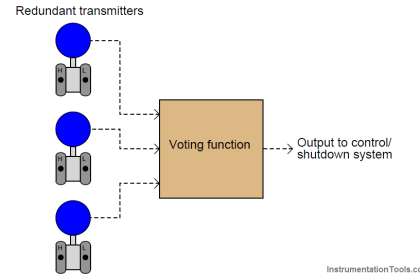
- Addition of redundancy instruments (1oo2, 2oo3)
- Introduction of bypass valves for testing if new On/Off or Control valves are provided
- Requirement Design for automated online testing
- The necessity of special tools or equipment like “partial stroke test devices”
- Inclusion of software to collect the data when an online check is possible
- Accessibility needs to perform testing
How to do a Proof Test?
Performing SIS proof tests & method of the test varies with the configuration of SIS sensors, Final control elements (viz. 1oo2, 2oo3, 2oo2, etc), and their model details (Ex. Orifice based pressure, Differential pressure/level, Radar level, Inline Mass/Vortex flowmeters, etc) and Pneumatic operated/Electrically operated valves.
However, below basic procedures can be performed on the sensors at calculated frequency. This may be as early as 2.5 to 3 years even if the proof test is calculated as 5 or 6 years.
| S.no | Type of test | Outcome |
| 1 | Visual inspection of field transmitters | This will reveal problems that are not identified by the instrument self-diagnostic tests. The instrument will remain available for its function. |
| 2 | Wetted part inspection (process lines) | The instrument will remain available for its function. |
| 3 | Visual inspection of Flowmeter configurations | Time constants and/or K factors may get disturbed in Intelligent flow instruments if the proper soft lock is not programmed. |
| 4 | Visual inspection of Control valves | If there are leaks in the Air filter regulator, booster relays can be corrected If there are solenoid valve coil damage, air leak from the spools, and end connections the same can be conducted. |
Cautions for Proof Test Methods
Proof test plan to be developed cautiously taking into consideration
- Check if proof testing in the field is acceptable from a process point of view as per the plant area layout/piping routing/chemical hazards. Consider the below factors-
- Electrical area classification
- Toxicity
- Ability to isolate reliably without impacting the run plant
- For in-field test procedures: Confirm if all the required hardware (such as isolation or by-pass valves) either exists in the design or is to be added to the design.
- Determine if the process application requires any modifications to the SIS instrument Maintenance procedure (for example, whether testing can get impacted due to an incompatible test fluid).
- Changes to the application program require full validation and a proof test of any SIF impacted by the change
Ways to Improve SIS Proof Testing
- SIS Design to ensure that field transmitters/Final control elements are having redundancy as far as possible to perform Proof testing. This is based on the best Engineering practice and the results obtained with PFD calculations.
- For inline flow measurement instruments ‘Heartbeat’ or ‘Smart meter verification’ self-diagnostic sensor technology facilitates timely and accurate diagnosis of instrument o faults. These tests can do diagnostic coverage of up to 98%.
- Results of Inline flowmeter test results to –
- Enable targeted, timely, and cost-effective maintenance interventions
- Ensure safe processes with minimal process interruption
- Drive cost-effective maintenance through smart data and diagnostics
- If there are deficiencies found during the proof testing shall be repaired in a safe and timely manner. A proof test shall be repeated after the repair is completed at some periodic interval (without disturbing the process), the frequency of testing shall be re-evaluated based on various factors including historical test data, plant experience, and hardware degradation.
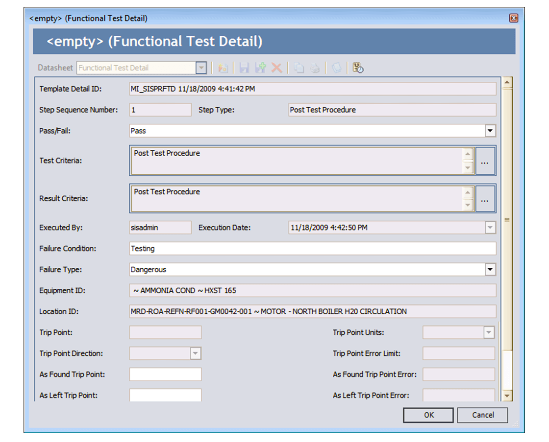
Documentation Requirements
- Documenting the results of routine and ongoing proof testing is very important to ensure a safe operation.
- All the test reports shall be saved in the plant Management Information System.
Details of records shall be
a) Description of the tests and inspections performed including identification of the test procedure used
b) Date of the individual tests and inspections performed on the SIS instrument/valves.
c) Name of the technician who performed the tests and inspections
d) Serial number of the instrument or Plant identifier of the system tested (e.g., loop number, tag number, equipment number, and SIF number)
e) Results of the tests and inspection including the “as-found” condition, all faults found (including the failure mode), and the “as-left” condition.
- Maintaining proper documentation (preferably in electronic format) is vital even if there is a need for Equipment Damage claims if any.
Reference:
IEC 61511: “Functional safety – Safety instrumented systems for the process industry sector”
If you liked this article, then please subscribe to our YouTube Channel for Electrical, Electronics, Instrumentation, PLC, and SCADA video tutorials.
You can also follow us on Facebook and Twitter to receive daily updates.
Read Next:
- SIS Design
- SIL Verification
- Common Cause Failure
- Intrinsic Safe Calculation
- Safety Requirement Specification