Relay logic is a method of implementing combinational logic in electrical control circuits by using several electrical relays wired in a particular configuration.
Relay Logic
The schematic diagrams for relay logic circuits are often called line diagrams, because the inputs and outputs are essentially drawn in a series of lines.
A relay logic circuit is an electrical network consisting of lines, or rungs, in which each line or rung must have continuity to enable the output device.
A typical circuit consists of a number of rungs, with each rung controlling an output. This output is controlled by a combination of input or output conditions, such as input switches and control relays.
The conditions that represent the inputs are connected in series, parallel, or series-parallel to obtain the logic required to drive the output. The relay logic circuit forms an electrical schematic diagram for the control of input and output devices.

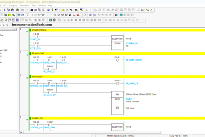
Figure – Example Ladder Logic Diagram
Relay logic diagrams represent the physical interconnection of devices. Each rung would have a unique identifying reference number and the individual wires on that rung would have wire numbers as a derivative of the rung number.
Thus, if a rung was labelled as 105, the first independent wire would be 1051, the second as 1052, and so forth. A wire would be named for the top most rung to which it connected, even if it branched to lower rungs.
When designing a system, it was common practice to skip numbers for the rungs to allow later additions as required. When the rack was manufactured, as a wire was installed, each end would be marked with wire labels (a.k.a. wire markers).
This also applied for pulling wire into the factory through conduit or in trays where each wire would have corresponding numbers. Wire labels were typically pieces of white tape with numbers or letters printed onto them and collected in small, pocket sized booklets.
A number strip would be peeled out and wrapped around the wire near the end. Wire numbers were made up of a series of the number strips so wire 1051 would be four strips. There are also pocket sized printers that print onto an adhesive backed label that can be wrapped around the wire.
The basic format for relay logic diagrams is as follows:
- The two vertical lines that connect all devices on the relay logic diagram are labeled L1 and L2. The space between L1 and L2 represents the voltage of the control circuit.
- Output devices are always connected to L2. Any electrical overloads that are to be included must be shown between the output device and L2; otherwise, the output device must be the last component before L2.
- Control devices are always shown between L1 and the output device. Control devices may be connected either in series or in parallel with each other.
- Devices which perform a STOP function are usually connected in series, while devices that perform a START function are connected in parallel.
- Electrical devices are shown in their normal conditions. An NC contact would be shown as normally closed, and an NO contact would appear as a normally open device. All contacts associated with a device will change state when the device is energized.
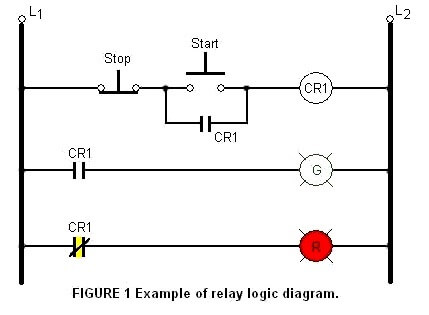
Figure 1 shows a typical relay logic diagram. In this circuit, a STOP/START station is used to control two pilot lights. When the START button is pressed, the control relay energizes and its associated contacts change state.
The green pilot light is now ON and the red lamp is OFF. When the STOP button is pressed, the contacts return to their resting state, the red pilot light is ON, and the green switches OFF.
Relay logic design
In many cases, it is possible to design a relay logic diagram directly from the narrative description of a control event sequence.
In general, the following suggestions apply to designing a relay logic diagram:
1. Define the process to be controlled.
2. Draw a sketch of the operation process. Make sure all the components of the system are present in the drawing.
3. Determine the sequence of operations to be performed. List the sequence of operational steps in as much detail as possible. Write out the sequence in sentences, or put them in table form.
4. Write the relay logic diagram from the sequence of operations.
If you liked this article, then please subscribe to our YouTube Channel for PLC and SCADA video tutorials.
You can also follow us on Facebook and Twitter to receive daily updates.
Read Next: