Industrial Process Plant Projects include several electrical consumer types including motors, heaters, actuators, etc, and for driving such items dedicated control and power circuits are installed in MCC room(s).
The control circuits usually have signal interfaces with Digital Control Systems (including DCS, ESD, PLC, …) for transferring the command signals to MCC circuits and returning the acknowledged ones from MCC Circuits. Such MCC signal interfaces may be implemented by two usual formats as using hardwired signals or using serial links (communication).
The most common and usual practice of such MCC signal interfaces is transferring the signals by hardwired format. For this format of signal transfer, there are some termination considerations that will be discussed in more detail as title of MCC Signal Interface Termination (MCC-SIT).
Motor Control Center (MCC)
In the process plants, there are so many electrical consumers (including motors, heaters, actuators, …) that shall have some signal interfacings with Plant Digital Control Systems (DCS, ESD, PLC, …) for transferring commands and returning the acknowledges.
For implementing relevant power and control circuits of such electrical consumers, some dedicated areas (including physical area, panels or cabinets, circuits, …) for driving the collection of consumers. This area is usually assigned as the Motor Control Center (MCC). Most of the process consumers are motors, so the selected title refers to Motor Control Center but usually (and in practice) it includes all electrical consumer types (see Figures 1 and 2).
It shall be noted that each industrial project plant may have some other different electrical consumers than Process Electrical Consumers (which usually don’t have any direct signal interfaces with Plant Digital Control Systems) and they will have dedicated areas, panels/ cabinets, and circuits separate from MCC. Lightings and power sockets distributed in the project site are examples of such electrical consumers.
Motor Control Center (MCC) is related to different concepts or definitions as explained below (see Figure-1):
MCC Circuit:
The Power and Control Circuits are provided to drive power to each electrical consumer (motor).
MCC Cell:
The physical (cubic) cell feeder for installation of each MCC Circuit.
MCC Panel / Cabinet:
Panel or Cabinet including the installation arrangement of several MCC Cells.
MCC Type:
MCC Panels / Cabinets may be constructed in two types:
- Fixed Type (fixed cubical area with hinged door), and
- Withdrawable Type (see figures 1 and 2).
MCC Room:
The physical room for the installation of MCC Panels / Cabinets.
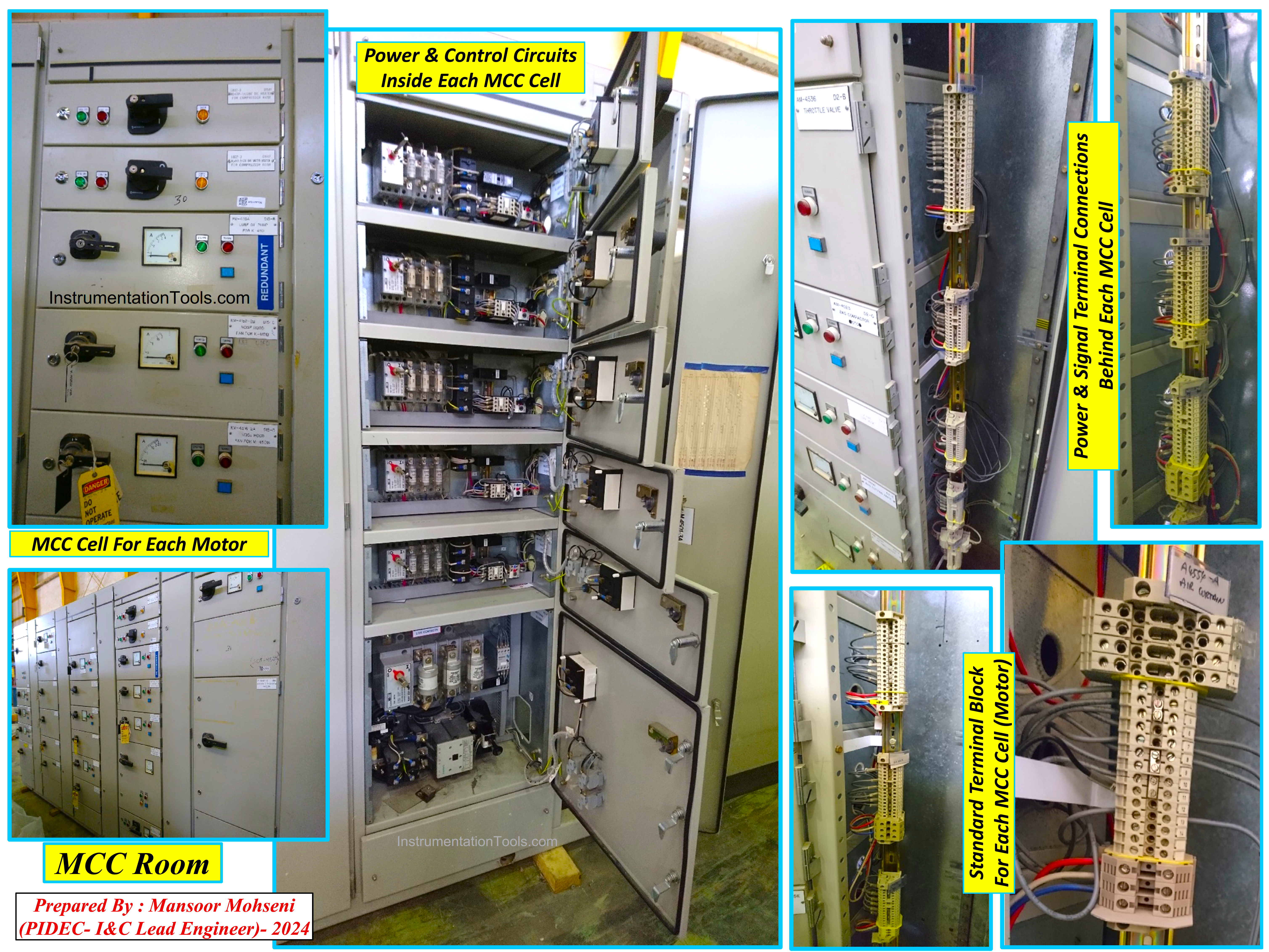
Figure-1: Fixed Type MCC (With clarification on different MCC concepts)
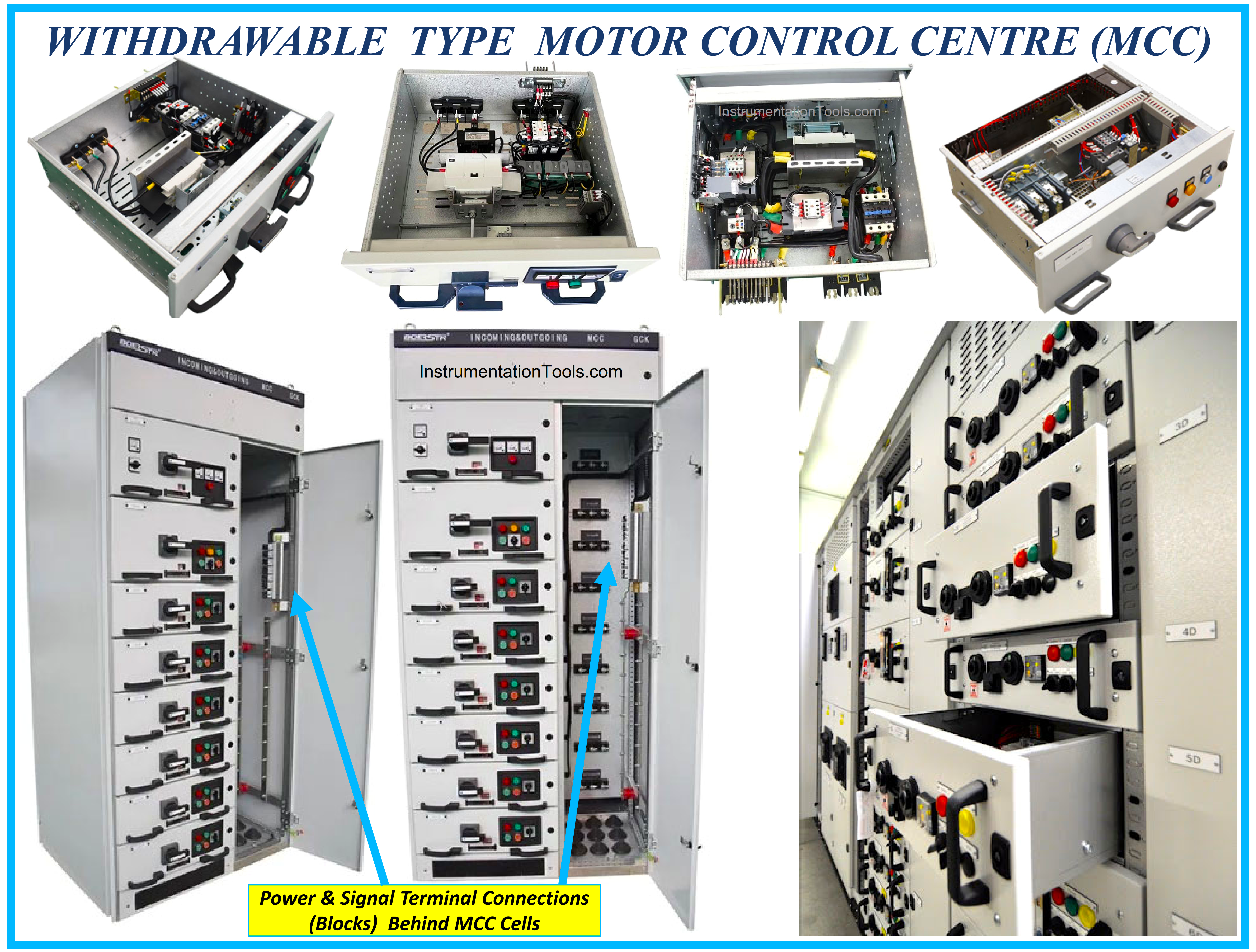
Figure-2: Withdrawable Type MCC (with extracted cells shown)
MCC Standard Terminal Blocks:
Usually, MCC cells are designed and constructed with standard terminal blocks (for quantities, sizes, and formats) in order to provide similar connection templates and to ease the operator actions, even in practice some terminals may be not used or connected for some electrical loads.
MCC Standard Circuits Design:
Usually, different MCC circuits (cells) will be designed and constructed in some limited standard types. Further to making uniformity in operation checking and troubleshooting activities, such standard consideration will help site electrical operators to change or substitute MCC cells by new ones (for similar electrical loads).
Figure-2 shows, that in the case of a problem in each MCC cell, site electrical operators can easily and quickly change the faulty cell with a similar spare cell. After maintenance of a faulty MCC cell, it can be returned to its position or it can be considered as a new spare.
Power Control Center (PCC) / Power Switching:
The Panels / Cabinets and all relevant equipment for switching and distributing the main Electrical Power Feeders are installed in the Power Control Center or Power Switching Room. This area or room provides suitable main power feeders to High Load Consumers or feeders of collection of loads (as an example MCC Cabinets).
Since the function facility of this room changes the transfer supply paths to different loads (similar to switchgear) sometimes it is called a Switchgear Room too.
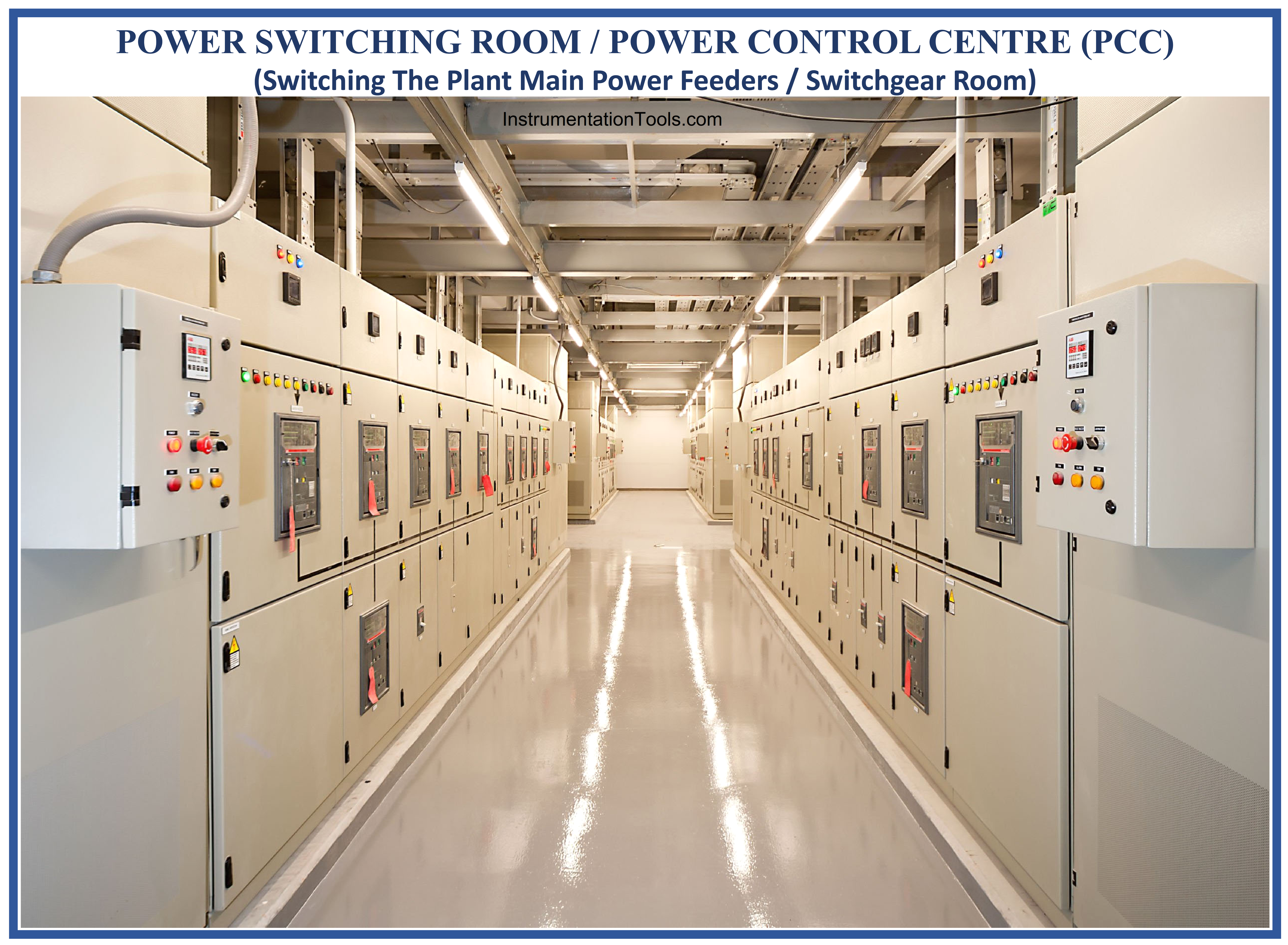
Figure-3: Power Switching Room / Power Control Center
Electrical Substation (Building):
In the process plant, the building arrangement of the Power Control Center (PCC) and Motor Control Center (MCC), is usually called an Electrical Substation (Building). Although this building or area has very common facilities similar to Power Stations (which are also called Substation), but it has some differences with Power Stations.
Some Process Plants may include Power Stations too, in which such stations are called Substation, while the building of arrangement of PCC and MCC is called a Switchgear Room (or even MCC Room).
In Some Process Plants, the assignment of Buildings may be selected from one of the mentioned titles or some similar titles. Nevertheless in each Process Plant, we have some area for MCC and some area for power switching (and maybe some area for High Voltage/ Power Inputs) facilities.
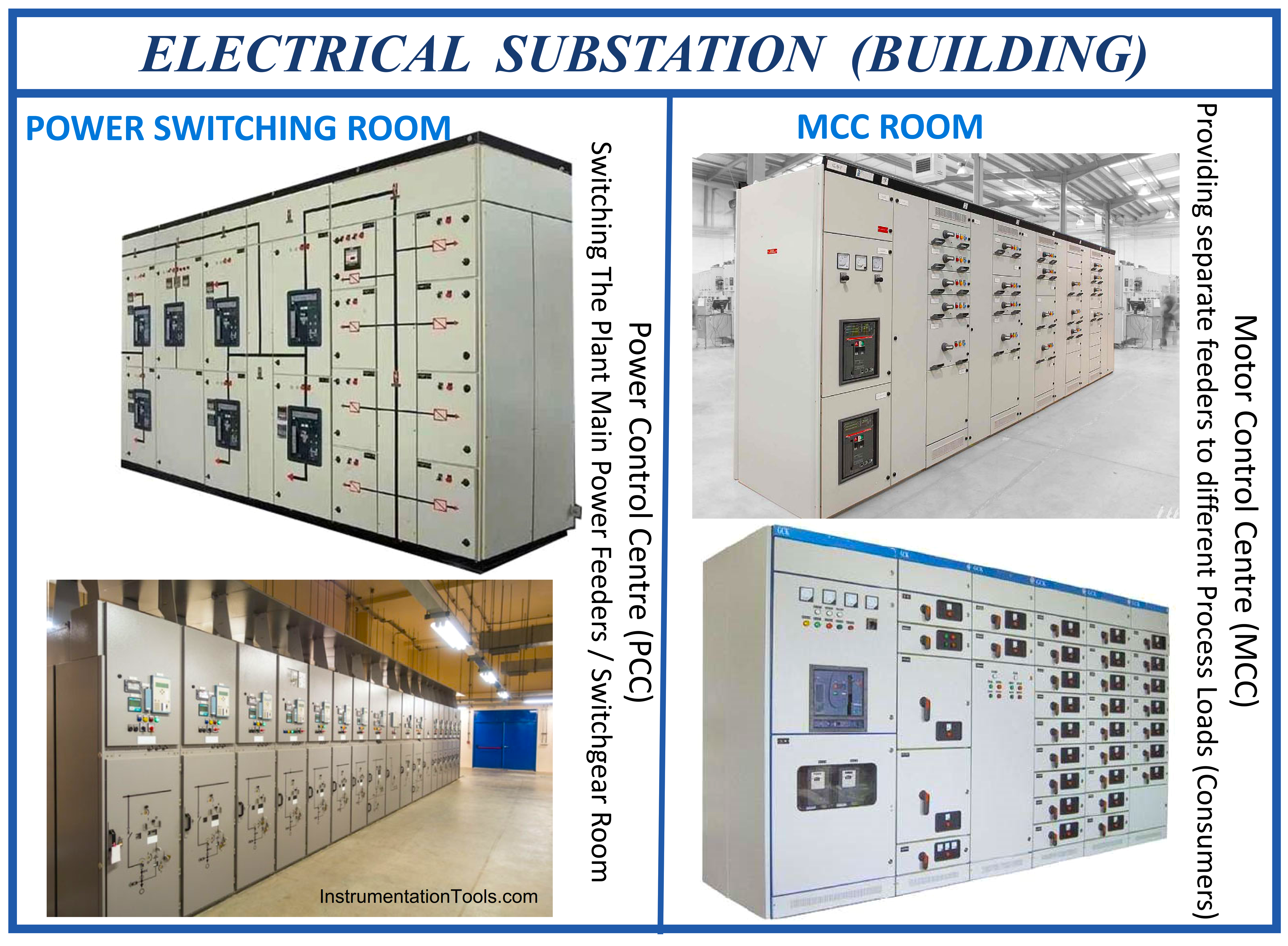
Figure-4: (Process Plant) Electrical Substation Building
Package MCC and Power Distribution Circuits:
Package Control Panels / Cabinets considered for Process Packages of Industrial Projects (based on plant control philosophy) sometimes include Power Distribution and MCC Circuits for their electrical consumers, but generally, such panels or cabinets don’t have MCC circuits and they use Process Plant MCC for switching on/ off or drive control of relevant electrical consumers. In fact, usually, such panels or cabinets will have Signal Interface Termination (SIT) with MCC similar to other Digital Control Systems.
Figure 5 shows some examples of Package Control Panels / Cabinets that have areas for Power Distribution and MCC Circuits. This area sometimes may be one area section of each panel or cabinet, and sometimes a dedicated panel(s) or cabinet(s) may be considered for such facilities. However as mentioned in Figure-5 usually such package control panels/cabinets will drive small electrical loads (and if such loads are big, the plant MCC will be used for load control).
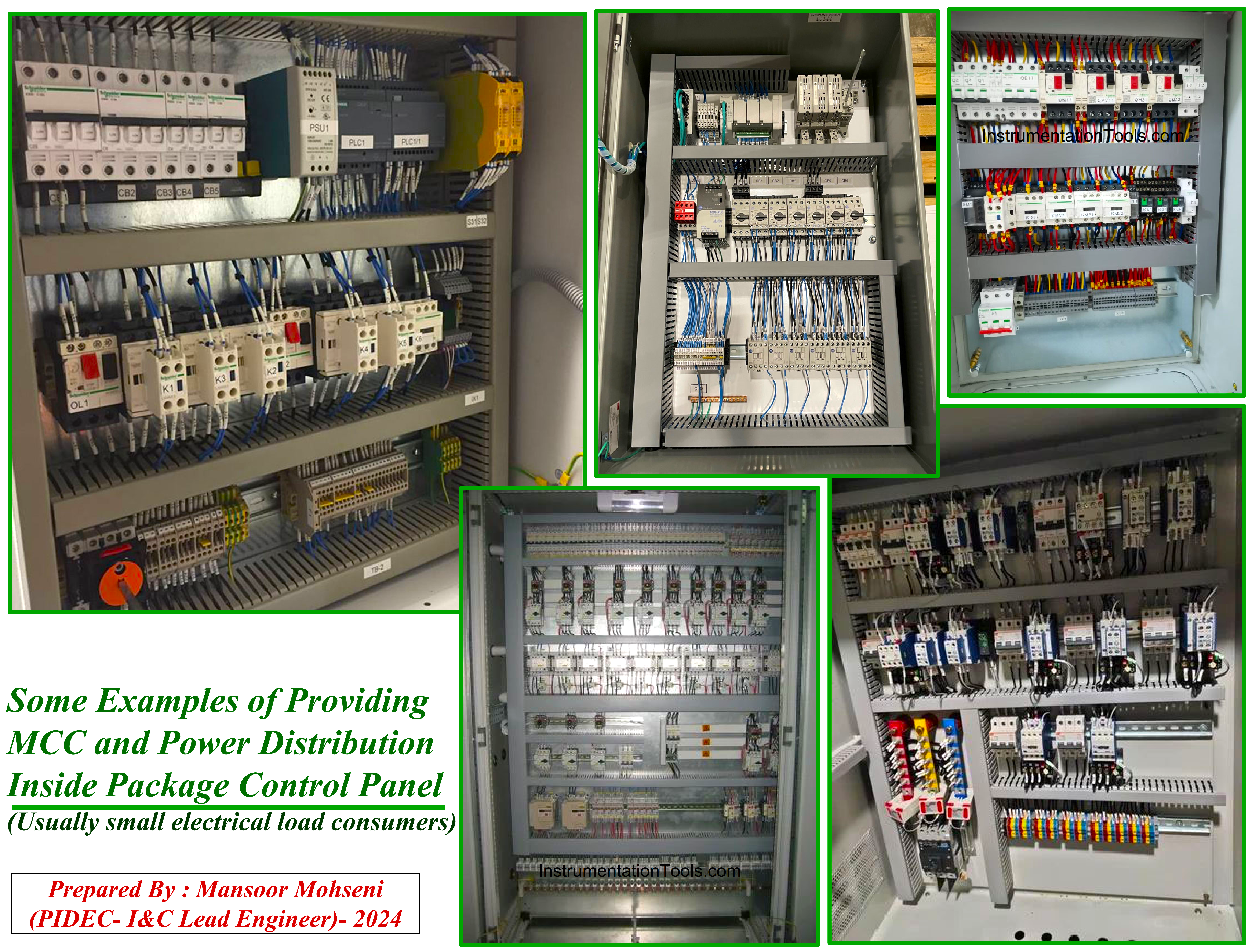
Figure-5: Some Examples of Providing MCC and Power Distribution inside Package Control Panel / Cabinet.
MCC Signal Interfacing Termination (MCC-SIT)
- As mentioned before, each MCC Circuit (Cell) for driving one electrical load (usually) has dedicated standard Power and Signal Terminal Blocks behind the MCC Cell. So it can be concluded that for each MCC Cell, at least one Multi-pair signal cable is to be considered for transferring signals with Digital Control Systems (DCS, ESD, PLC, …).
- However, Digital Control Systems have input and output terminal connections based on I/O Terminal Boards. On the other hand, usually, all the input signals will be gathered near each other (in one terminal block) and similarly output signals will be transferred outside with the considered terminal block. So some external facility is required to combine Digital Control System input and output signals relevant to each MCC Cell by cross-wiring and arranging them in one dedicated terminal block (for connection to above mentioned Multi-Pair cable). Here it shall be mentioned that the explanation is applicable to normal IO signals of Digital Control Systems, while some of such systems have definable IO channels (which is not our concern here).
- Another important consideration is that some MCC Cells will have Signal Interface Termination (MCC-SIT) connection with more than one Digital Control System (for example DCS and ESD). In such cases also need an external facility to combine and arrange different Digital Control System Signals and collect them in one terminal block.
- Control circuits of MCC cells operate with AC voltages (220 VAC or 110 VAC) while usually IO signals of Digital Control Systems are considered as 24VDC. So for transferring Digital Control Systems Signals to MCC Control Circuits, we need isolation relays to change the voltage types and levels. These relays may be installed inside MCC cells or between Digital Control Systems IO and MCC cells (i.e. MCC-SIT Panels/ Cabinets or even inside the marshalling panels/ cabinets of Digital Control Systems).
- The above-mentioned relays will have a first-level isolation role between high (220 or 110) AC voltage and Low (24) DC voltage. In fact, some design companies prefer to consider such relays inside the MCC Cells to guarantee the Digital Control Systems side will surely have just 24 VDC (safe voltage!).
- Further to considering such relays inside MCC Cells, some designers (or due to client requests) prefer to add additional second-level isolation relays during the transfer path (MCC-SIT Panels/ Cabinets) or inside Marshalling Panel/ Cabinet of Digital Control Systems.
- In any of the above-mentioned cases, using MCC-SIT Panels / Cabinets will provide good facilities for implementing any desired control philosophy.
- MCC Cells (or accordingly MCC Panels/ Cabinets) are located in different locations inside the MCC Room (and especially in big process plants that have so many MCC cells) it will be a good facility to consider one location point for connection of MCC signal interfaces (which is the location of MCC-SIT Panels/ Cabinets). By such consideration cabling inside the MCC Room can be done and completed regardless of field/ site cablings. This consideration also has good advantages when MCC signal interfaces will come to the MCC room from several Digital Control Systems or Package Control Panels/ Cabinets located (installed) at different field/ site positions.
- MCC-SIT Panels / Cabinets can properly define the battery limit of activities between EL (Electrical) and I&C (Instrumentation & Control) Teams.
Types of MCC Signal Interfacing Terminations
Based on project conditions and plant control philosophy design the following approaches can be considered for MCC-SIT Panels / Cabinets.
Case-1) Simple MCC-SIT:
When the Substation Building (MCC Room) and Control Building (Digital Control Systems Cabinets Room) are very close to each other (or constructed behind each other) the best practice is to consider first-level isolation relays inside MCC cells and the cable of MCC Cell Standard Terminal Block directly connected to provided MCC-SIT Terminal Blocks either in separate MCC-SIT Panel/Cabinet inside Control Building or even in Marshalling Panels/ Cabinets of Digital Control Systems (based on agreements with Digital Control Systems Vendors). However in this case one set of panels or cabinets is required for arranging different MCC Signal Interfaces with Package Control Systems (MCC-SIT) inside the Control Building (or MCC Room).
Case-2) Interposing Relay Panel (IRP) as MCC-SIT:
When the Substation Building (MCC Room) and Control Building (Digital Control Systems Cabinets Room) are far from each other, then good practice is to use multi-pair cables for transferring interface IO signals between the MCC Room and the Control Building.
In this case, one set of Interposing Relay Panels (IRP) will be considered as MCC-SIT Panels/ Cabinets in which the suitable arrangement of terminal blocks will be provided by cross-wirings between different types of Digital Control System IO signals.
Figure 6 shows two types of sample IRP which are located in the MCC Room. Two main sides of such panels (Digital Control System IO side and MCC Cell Terminal Block side) are specified in this figure to better understand the cross wirings made inside the panels. Please notice that such cross-wirings are hidden inside the panel ducts.
Also please notice to Input/ Output Terminal Boards of Digital Control Systems (and set of Inputs or Output Signals) which are combined in the MCC Standard Terminal Block side of the panel (for each dedicated MCC Cell). It shall be noted that the IO boards of Digital Control Systems are located/ installed at the Control Building and just the IO terminal boards are used inside the IRP.
The type of considered relays inside the Interposing Relay Panels (IRP) panel shall be confirmed by the design Engineering Company, especially for checking on signals related to SIL-related loops (please see two types of different relays shown in Figure-6).
In this case further to IRP panels/ cabinets for Digital Control Systems, additional panels/ cabinets are required for arranging Signal Interface Termination of Package Control Systems to MCC cells (if the number of Package Control Systems is limited the required SIT may be implemented inside Considered SIT’s for Digital Control Systems).
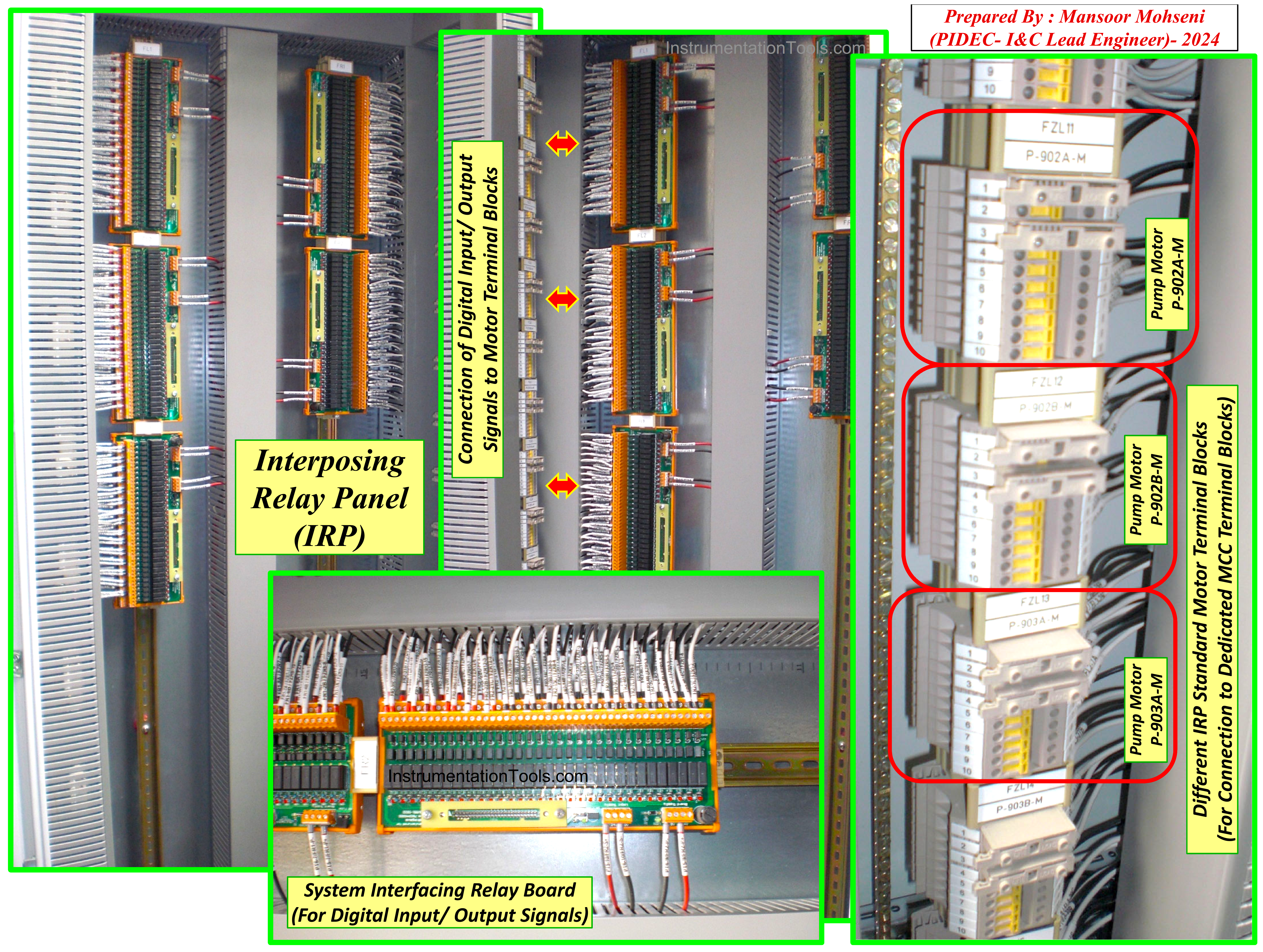
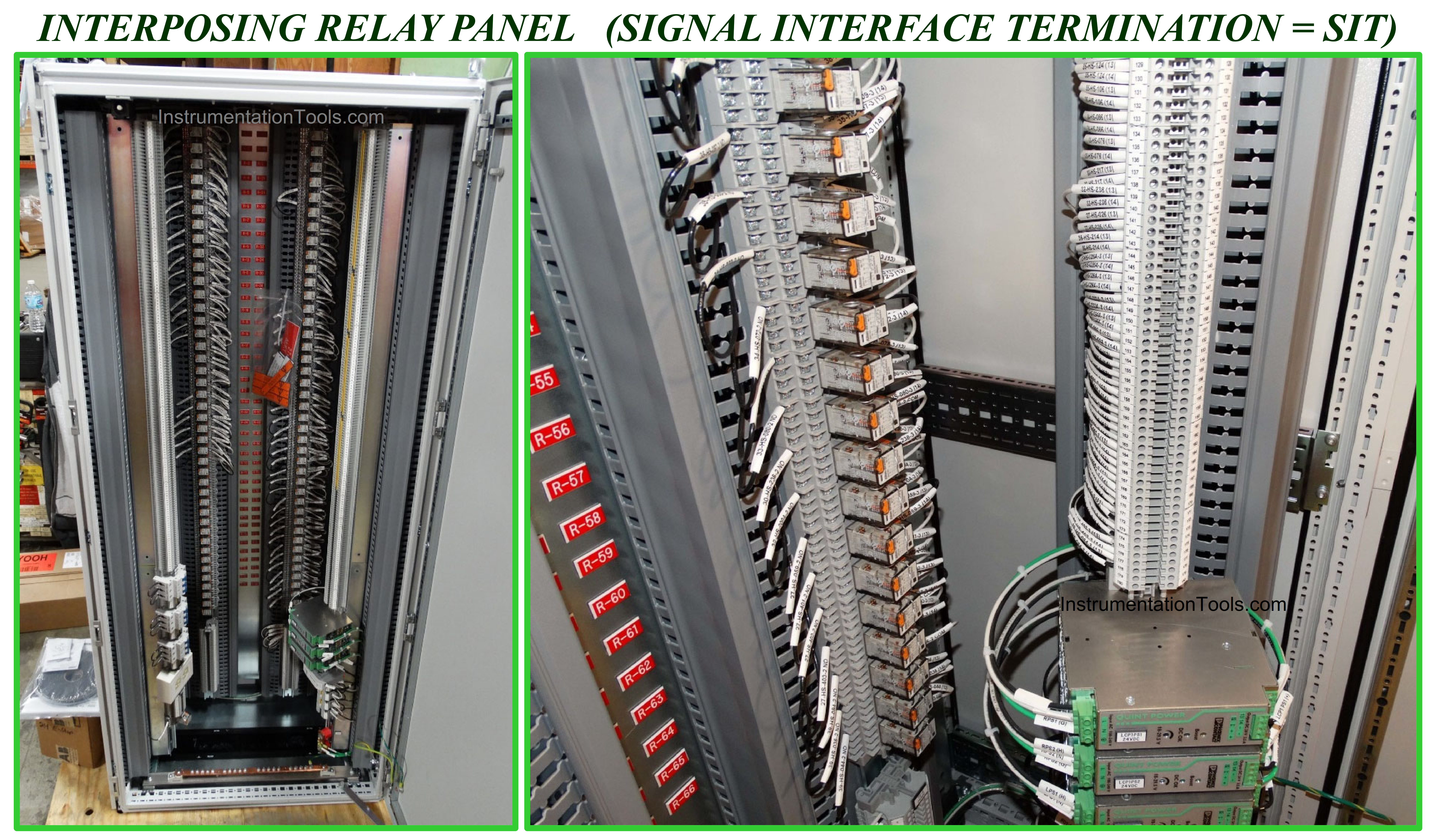
Figure-6: Examples of two samples of IRP (Interposing Relay Panels) used as SIT (Signal interface Termination) Panels/ Cabinets.
Case-3) Remote IO Panels/ Cabinets as MCC-SIT:
When the Substation Building (MCC Room) and Control Building (Digital Control Systems Cabinets Room) are far from each other, then another good practice is using Remote IO panels/ cabinets for transferring interface IO signals between the MCC Room and the Control Building.
In this case, the MCC Signal Interfaces are directly connected to the Digital Control Systems inside the MCC Room and just communication cables are needed for Links between the Remote IO Panels/ Cabinets and main / master controllers of the Digital Control Systems.
For long-distance paths between the MCC Room and the Control Building or for guaranteeing safe reliable communication links, usually the required communication media are considered as Fiber Optic. However in this case Remote IO panels/ cabinets will do the role of SIT panels/ cabinets (with considering isolation relays inside it with the above-mentioned arrangement). However in this case for a high quantity number of Package Control Systems, we need additional SIT Panels/ Cabinets for them.
In this case, suitable Instrumentation/ System Earth further to UPS power supply feeders shall be provided for Remote IO panels (which are not easy in some industrial projects and may cause some problems).
Case-4) Dedicated Controller Panels/ Cabinets as MCC-SIT:
This case is completely similar to case-3, but in this case, instead of Remote IO Panels/ Cabinets, complete (dedicated) Controller Panels/ Cabinets (including System and Marshalling Panels/ Cabinets) are installed in the MCC Room. In fact in this case IO cards of the Digital Control System will be installed in the MCC Room too. For this case also suitable Instrumentation/ System Earthing further to UPS power supply feeders shall be provided for Controller panels (which are not easy in some industrial projects and may cause some problems).
For mentioned cases 3 and 4 the interfacing signals to all MCC panels are gathered by hardwired at a single point (SIT Panels/ Cabinets) and then these signals will be transmitted by a serial link to the main Digital Control Systems (at the Control Building). Since serial links cause some delays in transferring MCC Signal Interfaces and accordingly some delays in implementing real (logic/ interlock) loops, so for very fast loop actions may cause some problems.
Nowadays the communication rate of serial links is so high, and so most of the usual (logic/interlock) loops don’t see any problems, but the Control System Engineer shall check (total) satisfaction of very fast loop requirements due to made some delays (even such delays may be low, but such so low values may be not acceptable for very fast loops and may cause some safety problems).
Hence Control System Engineer shall guarantee for maximum probable delays occurring in the (logic/ interlock) loops or otherwise shall provide hardware transfer of such signals directly to the main Digital Control Systems. Another possible solution for such cases may be the use of a High-Speed Link with aware of the limited quantity of signals handled by such links.
MCC-SIT Panels/ Cabinets Roles in Plant Process Control Philosophy
Figure-7 shows a typical applicable Plant Process Control Philosophy for an Industrial Project Process Plant. As this figure shows some Power Feeders and some Signal Interfaces are the connection requirements between the Substation Building (Switching/ MCC Rooms) with Plant Process Fields and also the Plant Control Building(s).
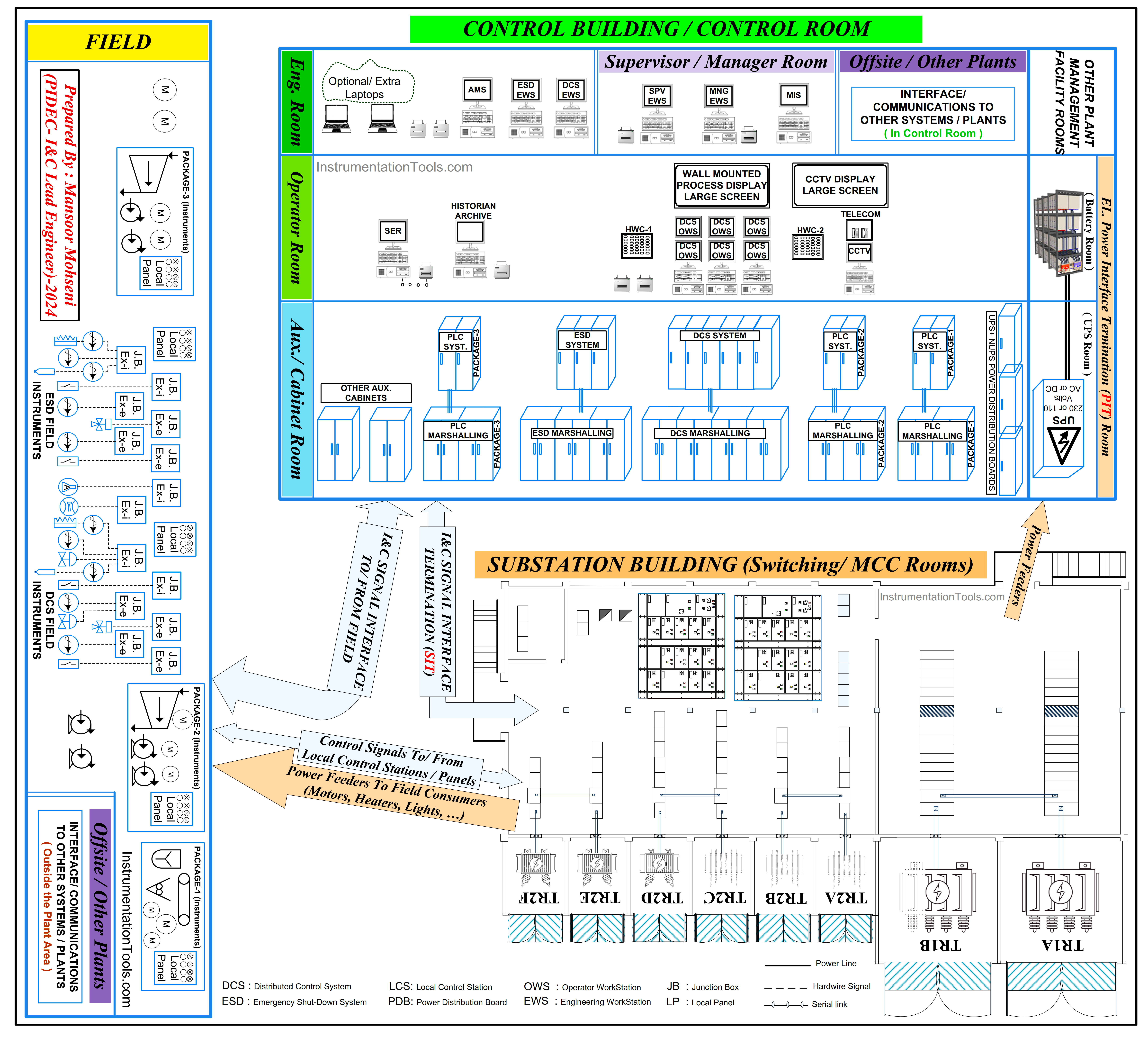
Figure-7: Substation Building Interfaces with Control Room and Plant Process Field (The Role of MCC-SIT in Plant Process Control Philosophy)
On the other hand, all Field Electrical Consumers will receive power feeders from the MCC Room, and some consumers (mainly motors) will have some local control stations to provide interfaces between field operators and MCC circuits. Furthermore, Digital Control Systems will have some interface signals with MCC panels for transferring command and feedback signals.
Also, some power connections from the MCC Room (or Substation Building) will provide feeders to required UPS Systems (with relevant Battery Package) in order to make stable power supplies for Digital Control Systems.
Installation Location for MCC-SIT Panels/ Cabinets
Regardless of the types of MCC-SIT Panels/ Cabinets (which are explained above), we need some locations for installing such panels/ cabinets inside or behind the MCC Room (Substation Building).
Again it should be reminded that defining such an installation point will clarify the battery limits of I&C and Electrical (EL) activities and will speed up the site construction activities and cablings. However, for such installations, we may find 3 cases.
Installation Case-I: MCC-SIT Panels/ Cabinets Inside MCC Room:
In most Industrial Process Plant Projects, the MCC-SIT Panels/ Cabinets are installed inside the MCC Room.
Figure-8: Installing MCC-SIT Panels/ Cabinets inside two typical MCC Rooms (Substation Buildings) based on the Industrial Project Scale Size.
Figure-8 shows the installation of MCC-SIT Panels/ Cabinets inside two typical MCC Rooms (Substation Buildings) based on the Industrial Project Scale Sizes. The two buildings are shown here based on a realistic Industrial Project and the real installation location of subject panels/ cabinets (in the large-scale project) can be found in Figure-9.
Figure-9: Realistic Installing MCC-SIT Panels/ Cabinets inside Large Scale Industrial Project MCC Room (Substation Building).
Figures 8 and 9 show the MCC-SIT panels/ cabinets that are installed inside the MCC Room with the mentioned advantages. However such cases will have some problems: They are
- The MCC-SIT Panels/ Cabinets are in the scope of responsibility of the I&C-Team while the MCC Room (Substation Building) area is in the scope of control and responsibility of the electrical (EL) Team. So for wiring terminal connections, and any future plant activities like panel/ cabinets checking, maintenance and troubleshooting, or periodic monitoring, the I&C-Team shall do their work in the presence of the EL-Team. However, any problem with such panels/ cabinets during normal operations of the project plant (with the absence of the I&C-Team inside the MCC Room) may cause some blame discussions.
- The Substation Building is an area that includes High Voltage risks and from a safety point of view, the I&C-Team shall not be alone inside such area (especially for new or unexperienced team personnel). This potential risk will be increased if the access way for such panels/ cabinets is too long or if cross-overs with a considerable area of the substation building (see figures 8 and 9 again).
- The cables for MCC-SIT Panels/Cabinets will enter for terminations from the Substation Cable Cellar Room (see Figure-9 again). At least for two types of MCC-SIT Panels/ Cabinets such cable quantities will be too many, and if the location of such panels/ cabinets imposes long overlaps between I&C Cables and Electrical (EL) Power Cables, then some electromagnetic interference may occur. For a better understanding the cabling situations in Substation Cable Cellar, please notice to different cases shown in Figure-10 and estimate or imagine the possible situations for big overlaps between I&C cables and EL Power
cables (for doing the cablings and the possible electromagnetic interference too).
Figure-10 : Some examples of Different Cable Cellar Rooms under Substation Buildings.
Installation Case-II: MCC-SIT Panels/ Cabinets Behind MCC Room:
In this case separate room behind the Substation Building is considered for installation area for MCC-SIT Panels/ Cabinets as shown in Figure-11. As Figure-11 shows, SIT Room is completely considered separate from MCC Room (area) and the access way to MCC-SIT Panels/ Cabinets don’t have any cross over with MCC Room. So I&C Team can access to their panels/ cabinets without any help need (presence) from EL Team.
Also since the location of SIT Room is considered as edge side of Substation Building, so it may be possible to consider separate cable routes for I&C Cables (in this case the cross over area in Substation Cable Cellar can be minimum).
The disadvantage of this configuration may be mentioned as just unsymmetrical (or complex) format of Substation Building and possibly considering separate HVAC system for SIT Room.
Figure-11: Using SIT Room behind the Substation Building (MCC Room) at edge side (one of three shown offered positions: A, B, C).
Installation Case-III: MCC-SIT Panels/ Cabinets in dedicated SIT-ROOM inside Substation Building:
In this case separate dedicated room inside the Substation Building is considered for installation area for MCC-SIT Panels/ Cabinets as shown in Figure-12. As Figure-12 shows, although SIT Room is part of Substation Building but it has separate and its own access way. Comparing this case with two previous options, it can be found that this case has no any disadvantages of those ones. In fact it has its own access way and completely dedicated to I&C Team responsibility, while the Substation Building is simple and one HVAC system may handle the requirements of all building rooms.
In fact this installation case is similar to installation case-I but design and construction of Substation Building has been done by more obsession and precision so that the SIT-Room has been located on the limit edge side of Substation Building with the possible facility of considering best cable route for I&C cables. Of course the size of the new Substation Building may be not exactly equal to installation case-I, and it may be slightly bigger than it.
By review and studying 3 installation cases, it seems that the last installation case may be considered as best solution.
Figure-12: Using SIT Room inside the Substation Building (MCC Room) at edge side of Building with separate dedicated access way.
Instrument/ System Earthing Requirements for MCC-SIT Panels/ Cabinets
If the SIT Panels/ Cabinets don’t have Remote IO or dedicated controllers (as part of Digital Control Systems), usually no need to consider extra Earthing requirements than Electrical (Protection/ Safety) Earth which is easily accessible inside Substation Building.
On the other hand if SIT Panels/ Cabinets have Remote IO or dedicated controllers (as part of Digital Control Systems), further to Electrical (Protection/ Safety) Earth, extra Earthing as Instrument/ System Earthing is required. In fact it would be better that this Earth facility to be bonded to Instrument/ System Earthing provided around the Control Building. However this Earthing Facility shall be completely isolated from Electrical (Protection / Safety) Earthing facility inside Substation Building.
Considering separate Instrument/ System Earthing inside dedicated SIT-Room may can guarantee preventing wrong/ faulty connection of two mentioned Earthings inside the Substation Building (since by such case just I&C Team will have access for connection to considered separate I&C Earthing).
Figure-13 shows the good practice Electrical Earthing around the Substation Building further to I&C Earthing requirements inside SIT-Panels/ Cabinets (which contain Remote IO or dedicated Controller).
Figure-13: I&C System Cabinet Earthing Requirement + Best Practice for Substation Earthing (Electrical/ Protection).
Conclusion
For transferring MCC Signal Interfaces to Digital Control Systems of Process Plant Project, it is required to use SIT-Panels/ Cabinets which are installed inside Substation Building. The best practice is installing such Panels/ Cabinets inside separate dedicated room. Referring to Figure-7 we can define two concepts as below:
Figure-14: Defining two concepts: I&C SIT-ROOM Versus EL PIT-ROOM.
Considering separate dedicated I&C SIT-ROOM will have good advantages explained in the above article.
Since this concept is rarely used or defined in industrial projects, the valuable reader comments are highly appreciated.
References:
- Instrumentation and Electrical Teams Interactions
- Instrument Engineer Roles & Responsibilities in the Design Stage
- Instrumentation Engineer Activities & Documents in Detail Phase
- Instrumentation and Control Engineering in Project Packages
- Instrumentation Package Systems Architecture