Inst ToolsInst ToolsInst Tools
  • Courses
  • Automation
    • PLC
    • Control System
    • Safety System
    • Communication
    • Fire & Gas System
  • Instrumentation
    • Design
    • Pressure
    • Temperature
    • Flow
    • Level
    • Vibration
    • Analyzer
    • Control Valve
    • Switch
    • Calibration
    • Erection & Commissioning
  • Interview
    • Instrumentation
    • Electrical
    • Electronics
    • Practical
  • Q&A
    • Instrumentation
    • Control System
    • Electrical
    • Electronics
    • Analog Electronics
    • Digital Electronics
    • Power Electronics
    • Microprocessor
  • Request
Search
  • Books
  • Software
  • Projects
  • Process
  • Tools
  • Basics
  • Formula
  • Power Plant
  • Root Cause Analysis
  • Electrical Basics
  • Animation
  • Standards
  • 4-20 mA Course
  • Siemens PLC Course
Reading: AENT Module in Rockwell PLC – Remote IO Adapter
Share
Notification Show More
Font ResizerAa
Inst ToolsInst Tools
Font ResizerAa
  • Courses
  • Design
  • PLC
  • Interview
  • Control System
Search
  • Courses
  • Automation
    • PLC
    • Control System
    • Safety System
    • Communication
    • Fire & Gas System
  • Instrumentation
    • Design
    • Pressure
    • Temperature
    • Flow
    • Level
    • Vibration
    • Analyzer
    • Control Valve
    • Switch
    • Calibration
    • Erection & Commissioning
  • Interview
    • Instrumentation
    • Electrical
    • Electronics
    • Practical
  • Q&A
    • Instrumentation
    • Control System
    • Electrical
    • Electronics
    • Analog Electronics
    • Digital Electronics
    • Power Electronics
    • Microprocessor
  • Request
Follow US
All rights reserved. Reproduction in whole or in part without written permission is prohibited.
Inst Tools > Blog > PLC Tutorials > AENT Module in Rockwell PLC – Remote IO Adapter

AENT Module in Rockwell PLC – Remote IO Adapter

In Rockwell PLC, the most used network adapter for IO communication is the AENT module. Lets learn the detail technical specifications.

Last updated: October 30, 2023 9:41 am
Editorial Staff
PLC Tutorials
No Comments
Share
5 Min Read
SHARE

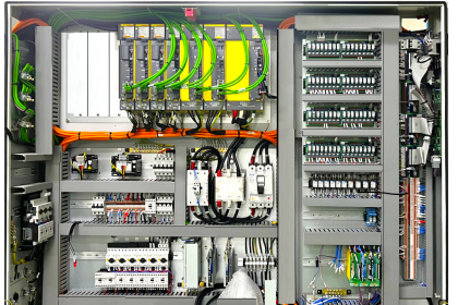
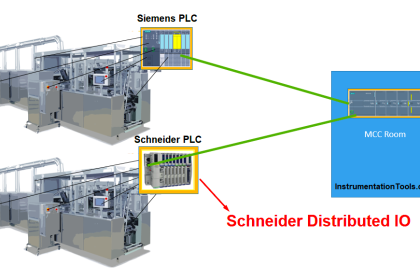
In industrial automation, there are three types of IOs – Local, Remote, and Distributed. It defines whether the IOs are in a local electrical panel or a remote network panel. It is decided based on the location of field instruments from the panel. Different types of automation manufacturers have corresponding modules in their make, for working with remote IOs.

Contents
AENT Module in Rockwell PLCIP Address ConfigurationLED DiagnosticsChassis Size

One such famous brand is Rockwell. In Rockwell PLC, the most used network adapter for IO communication is the AENT module. This module can be connected at a location other than the local PLC and is connected to it through Ethernet communication. The corresponding IOs are interfaced with the AENT module.

In this post, we will see the concept of the AENT module in Rockwell PLC.

AENT Module in Rockwell PLC

AENT Module in Rockwell PLC

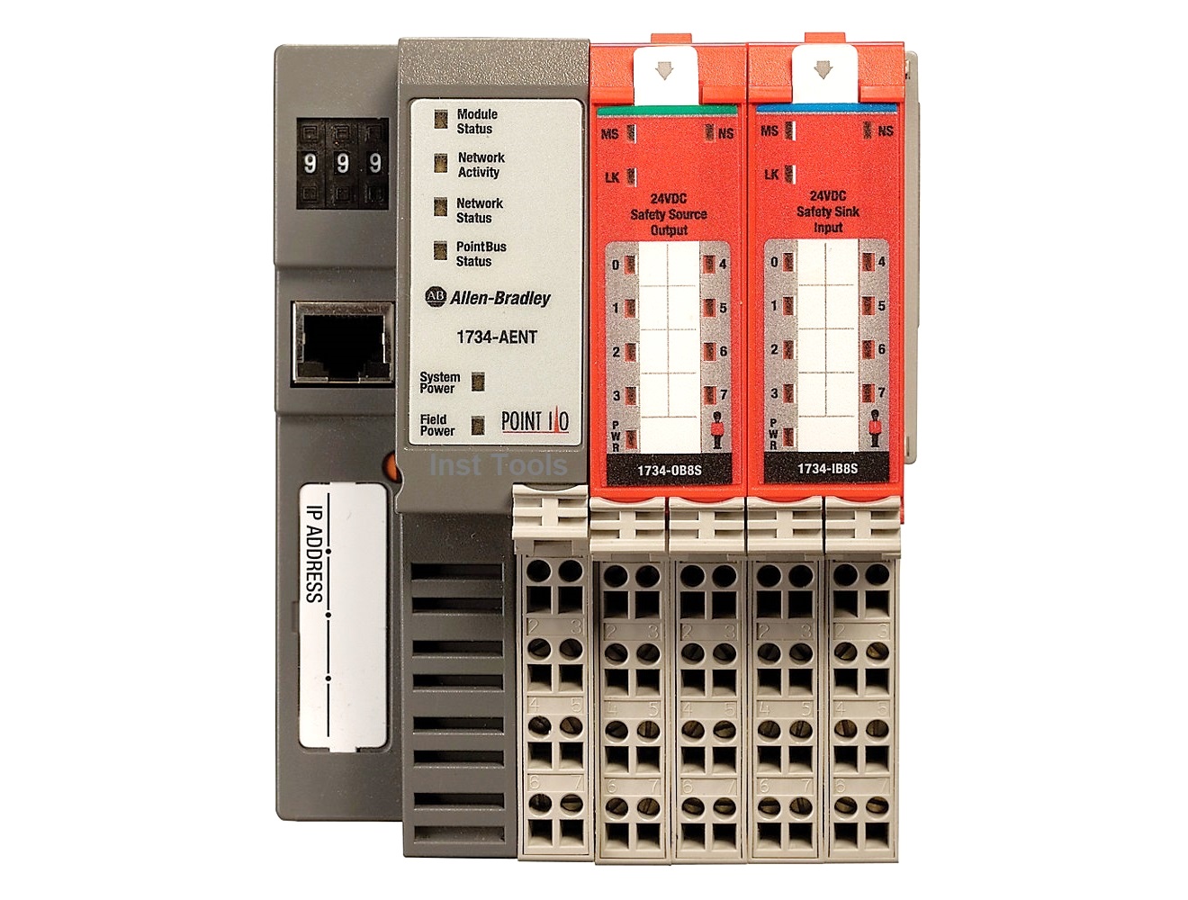
As discussed earlier, an AENT module is a type of remote IO adapter. The module does not have any CPU in it; it is just a network interface used to communicate field IO’s with the main PLC through Ethernet IP protocol. That means no logic can be written in the module as it will only read and write data of IO modules configured with it to the main PLC CPU.

You can connect a maximum of 64 IO modules with an AENT module, for interfacing. It is generally identified by the 1734-AENT series. Not only IO data, but you also get each and every diagnostic of the IO’s through this module. This makes troubleshooting much easier.

The module communication takes place through Ethernet IP protocol, and it has RJ45 ports in it for this. It can communicate in either half-duplex or full-duplex mode. The standard power supply for this module is 24V DC.

IP Address Configuration

There are three general methods through which IP address is set in the module –

  1. By setting the switches on it (it has three numbers which denote the last three digits of the IP address)
  2. Using BootP/DHCP software available from Rockwell
  3. Using IP configuration software available from Rockwell.

Once you set the IP address, you can then use the module for your communication with the main PLC.

In the PLC software (Studio 5000), the IO modules must be configured in this AENT module. These modules then communicate their IO status to the main CPU through the AENT module. This module can be used in star topology or tree topology.

LED Diagnostics

The module has the following LED in it for diagnostics – module status, network status, network activity, POINT Bus status, System power, and Field power. You can get a detailed description of each of the LEDs by reading its catalog. This helps in the detailed troubleshooting of the module.

One thing to be noted is that the power supply connected to the module can drive only a maximum of 10 IO modules; so, a power supply module is required after every 10 modules connected in the AENT.

Chassis Size

One of the most important terms related to this module is chassis size. Chassis size means the number of modules connected with AENT. For example, if 19 IO modules are used, then you must set the chassis size in the AENT configuration to 20.

The adapter stores this chassis size setting in non-volatile storage. When the adapter’s non-volatile chassis size does not match the actual number of modules present on its backplane, the adapter will not make any I/O connections. Also, once you are online, you are required to set this size online apart from offline configuration. After this step only you can use the module for communicating IO values with the main CPU.

AENT module is a higher range of adapter and so, is used only with three types of PLCs – Control Logix, Compact Logix, and Flex Logix. In this way, we saw the concept of the AENT module used in Rockwell PLC.

If you liked this article, then please subscribe to our YouTube Channel for Electrical, Electronics, Instrumentation, PLC, and SCADA video tutorials.

You can also follow us on Facebook and Twitter to receive daily updates.

Read Next:

  • Comparison of Control Loops
  • Top Best Practices of PLC Wiring
  • Interposing Relay Panel Wiring
  • Testing and Validation in PLC
  • Site Commissioning Steps for PLC
Don't Miss Our Updates
Be the first to get exclusive content straight to your email.
We promise not to spam you. You can unsubscribe at any time.
Invalid email address
You've successfully subscribed !

Continue Reading

How to use FIFO Block in TIA Portal? – Siemens PLC Programming
Motor Stop Interlock for Changing the Direction PLC Program
PLC Program for Password Management using Structured Text
PLC Programming for Multi-Color Sorting Conveyor System
PLC Memory Mapping and I/O addressing
Modbus Communication between Delta PLC with VFD
Share This Article
Facebook Whatsapp Whatsapp LinkedIn Copy Link
Share
Leave a Comment

Leave a Reply Cancel reply

Your email address will not be published. Required fields are marked *

Stay Connected

128.3kFollowersLike
69.1kFollowersFollow
210kSubscribersSubscribe
38kFollowersFollow

Categories

Explore More

Draw a Ladder Logic to switch ON-OFF a Bulb using a Toggle Switch ?
How to Wire a Field instrument to Control Room with Example
PLC Program for Automatic Parameter Initialization When Power UP
How to use PLC with SQL Database? – Basics & Tutorials
Interposing Relay Panel (IRP) – Wiring and Testing Requirements
Difference Between Wifi and Industrial Wireless
How to use JUMP Instruction in PLC Ladder Logic?
Glass Cutting and Polishing Machine: PLC Automation Solution

Keep Learning

PLC offline data of a project are compared

Compare Two Offline PLC Projects

Trolley and hoist PLC control

PLC Crane Movement Control with Limit Switches

PLC Multiple Choice Questions

PLC Multiple Choice Questions

memory types in siemens plc

#13 PLC Best Practices – Disable Unused Communication Ports

PLC Programming for Sequential Batch Mixing System

PLC Programming for Sequential Batch Mixing System

PLC Program for Traffic Light Sequence using Functional Blocks

PLC Program for Traffic Light Sequence using Functional Blocks

Delete Siemens CPU Memory

How to Delete the Siemens CPU Memory?

Learn PLC Programming

Basics of Ladder Diagram in PLC Programming

Learn More

Transformers Questions & Answers Part-2

Transformers Questions & Answers Part-2

Series Circuit

Series Circuit

non-contact pyrometers distance calculation

Non-contact Pyrometers Characteristics

Common Valve Abbreviations

Common Valve Abbreviations in US Engineering Drawings

Important Factors Consider during Piping Design

Important Factors Consider during Piping Design

How to Convert Cable Size from AWG to Inches

How to Convert Cable Size from AWG to Inches

Closed Tank Remote Seal Level Transmitter calculation

Remote Seal Transmitters Ranging Calculation

Conveyor and Puncher PLC Program

Toggle Switch & Sensor: Conveyor and Puncher PLC Program

Menu

  • About
  • Privacy Policy
  • Copyright

Quick Links

  • Learn PLC
  • Helping Hand
  • Part Time Job

YouTube Subscribe

Follow US
All rights reserved. Reproduction in whole or in part without written permission is prohibited.
Welcome Back!

Sign in to your account

Username or Email Address
Password

Lost your password?