This article provides the list of different types of Turbine Protective Devices like turbine over speed trip, low lube oil pressure, axial displacement, turbine temperature and turbine vibrations.
Turbine Protective Devices
- Tripping Device
- Low Lube Oil Pr.
- Over Speed Trip
- Low Vacuum
- SOV for remote tripping
- Hi/Lo Extrn. Pr.
- Casing Expansion
- Extrn./Exhaust Temp Differential Expansion
- Generator Protection
- Axial Displacement
- Manual/Remote Trip
- Bearing Vibrations
- Casing/Rotor Temp.
- Bearing Temperatures
Tripping Device
When ever the turbine is to be tripped , the Governing oil pressure is drained by tripping device. Thus pressure in front of stop valve piston disc and control oil pressure falls, resulting in closure of stop valve and control valves.
Over Speed Trip
The over speed protection is formed by three independent sensors of turbine speed evaluation that act through a selection of the output signal two of three after exceeding a set value of security speed for an immediate impulse for closing of the ESV within less than 30ms.

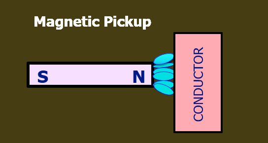
Magnetic Pickup
A magnetic pickup consists of a permanent magnet, wrapped with a coil of a few thousands turns of fine enameled copper wire.
When discrete ferromagnetic object such as gear teeth or blades are passed through the probes magnetic field, the flux density is modulated. This induces AC voltages in the coil. One complete cycle of voltage is generated for each object passed.
The total number of cycles will be a measure of the total rotation, and The frequency of the AC voltage will be directly proportional to the rotational speed of the shaft.


Making and breaking of the flux lines induces an alternating voltage into the coil around the pole piece.
Each pulse is represented by a gear tooth passing by the MPU. The impedance of MPU is approximately 220 ohms.
PROXIMITOR (Eddy Current Probe)
The mechanical energy is transformed into electrical energy using the proximity Transducer system. The interface device used for this system is called a proximitor. It generates a radial frequency(RF) signal using an oscillator circuit.
The RF signal is transmitted from the probe coil which creates an RF field around the probe tip. When conductive material is present in the RF field, Eddy currents flow in the surface of that material.
Once the probe is close enough to cause eddy currents to flow in a conductive material the RF signal is affected in two ways.
- Amplitude is minimum, when the Gap is less.
- Amplitude is maximum, when the Gap is more.
If the target is moving slowly within RF field, the signal amplitude will increase or decrease slowly. Depending on the movement of target, the amplitude increase or decrease slowly or rapidly. This oscillatory movements of the target causes the RF signal to modulate.

This will be convert by demodulator and will give a AC signal (sine wave). If the target is oscillating (gap changing slowly or rapidly), the proximitors output also vary the DC voltage (AC) shown above by a sine wave.
If the probe is observing a vibration, the proximitor will provide both a DC (gap) and an AC (vibration) component in the output signal. The frequency response from 0 Hz to 10 kHz.
Casing Expansion
This is the measurement of Turbine Casing or Shell moves in relation to a fixed location usually measured with a LVDT (Linear variable differential Transformer). Case expansion is the Thermal growth of the machine case as It expands during machine startup and on line operations.
Thermal growth at different rates can cause internal rubbing between rotating and stationary parts of the machine.
The case expansion transducer system uses the LVDT to measure the machine Case thermal growth.
A rod on the LVDT connects to the machine. As the machine case grows, the rod moves inside the LVDT. This causes a change in the signal in the LVDT.
Range:- 0 ~ 25mm; Trip:- 20mm
Rotor Expansion
During turbine startup, extra care must be taken to ensure that the case has been properly heated and expanded sufficiently to prevent contact between the rotor and the case.
For this Eddy probe transducer will generate a high frequency oscillating RF signals that is sent through the extension cable to the pickup tip. The pickup tip having a wound coil of fine wire, radiates a electromagnetic Field, as the radiated field is bisected by the rotor surface.
As the rotor surface moves closer to the pickup tip, a greater amount of eddy currents are created Proportional to the gap between the surface and the pickup tip. The signal sensor contains a demodulator which measure the increase in eddy currents, and generates an equivalent DC voltage proportional to the gap.
Rotor Expansion on a turbine is the absolute measurement of the rotor’s axial thermal growth with respect to the turbine’s foundation.
Differential Expansion
This is very important parameter receiving much attention during turbine startup and warming. This parameter measures how the turbine rotor expands in relation to the turbine shell or casing.
The difference between Casing expansion & rotor expansion is called differential expansion. It is the relative measurement of the rotor’s axial thermal growth with respect to the casing.
Differential Expansion on a turbine is the relative measurement of the rotor’s axial thermal growth with respect to the case. Casing expansion with respect to turbine’s foundation. Rotor expansion with respect to turbine’s foundation. Rotor expansion with respect to the casing is differential expansion
Range:- -4mm to 6mm
Alarm :- +2.30mm & -1.60mm
Trip:- +3.00mm & -2.50mm
Key Phasor
A transducer that produces a voltage pulse for each turn of the shaft, called the “KeyPhasor” signal. It produces a voltage pulse once each revolution.
Phase or phase angle, is a measure of the relationship of how one vibration signal relates to another vibration signal and is commonly used to calculate the placement of a balance weight.
This signal is used primarily to measure Shaft rotative speed and serves as a reference for measuring vibration Phase lag angle.
The keyphasor transducer is typically a proximity probe. The Keyphasor is a very useful tool when diagnosing machinery problems.
The standard scale factor is 200mV/mil or 7.87mV/um
1 mil = 25.4 microns
Rotor Axial Displacement
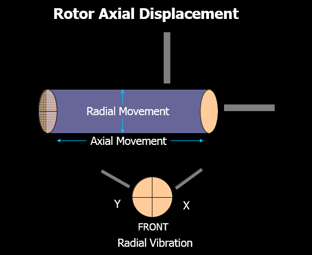
Two types of trips
- Rotor Axial Displacement
- Radial Vibration
The below table shows the alarm and trip values for bently nevada vibration measurement system.
| S.No | DESCRIPTION | Alarm | Trip |
| 1 | Key Phaser | — | — |
| 2 | Axial Displacement | +/- .5mm | +/- .8mm |
| 4 | Rotor Front Bearing | 120u | 180u |
| 7 | Rotor Rear Bearing | 120u | 180u |
| 8 | Gear Box Pinion Bearing | 100u | 180u |
| 15 | Gear Wheel Bearing | 100u | 150u |
| 16 | Alternator DE Bearing | 100u | 180u |
| 19 | Alternator NDE Bearing | 100u | 180u |
| 20 | Turbine Casing Expansion | 20mm | 25mm |
| 21 | Turbine Differential Expansion; Towards probe | +2.3mm | +3mm |
| 22 | Turbine Differential Expansion; Away from Probe | -1.6mm | -2.5mm |
Bearing Temperatures
Temperature of bearings is a measure of the how hot a bearing is operating. It may be due to overloading, misalignment, improper lubricant pressure and/or flow.
Nearly all turbine generator bearings were originally installed with bearing temperature sensors. These sensors may be thermocouples or RTDs. Any bearings that was not originally equipped with temperature sensors can be retro-fitted to accept thermocouples or RTDs.
| TURBINE TRIP- TEMP | |||
| DECRIPTION – Siemens Governor | I / O | SETPOINT | |
| TYPE | ALARM | TRIP | |
| TURB THRUST BRG TEMP BTM NEG | T / C | 110 | 120 |
| TURB BRG TEMP FRONT | T / C | 110 | 120 |
| TURB BRGTEMP REAR | T / C | 110 | 120 |
| GB PENION DE BRG TEMP | RTD | 100 | 110 |
| GB PENION NDE BRG TEMP | RTD | 100 | 110 |
| GB WHEEL DE BRG TEMP | RTD | 110 | 120 |
| GB WHEEL NDE BRG TEMP | RTD | 100 | 110 |
| GEN FRONT BRG TEMP | RTD | 85 | 90 |
| GEN REAR BRG TEMP | RTD | 85 | 90 |
Generator Protection
- Bearing and Winding Temperature
- Earth fault Protection
- Reverse/Low Forward Power
- Over Voltage / Under Voltage
- Over Frequency / Under Frequency
- Over Current
- Differential
- Neutral displacement
- Negative phase sequence
Note : Alarms and Trips Values may change from equipment to equipment.


useful information
Thanks very usful